FINAL TEST
Q1. What is the Compression ratio for the engine?
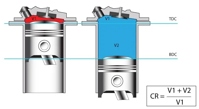
Compression ratio = Total Volume/Clearance Volume = (Vs+Vc)/Vc
Here, Vs - Swept Volume, Vc - Clearance Volume
The below plot shows the variation of cylinder volume with respect to the Crank angle.
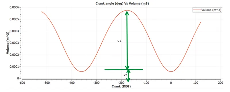
Stroke Volume: 
Clearance Volume: 
Using above values, CR = 11.06
Q2. Modify the compression ratio for this engine to 10.3 without changing geometrical parameters.
In order to change the CR without altering geometric parameters, total volume (geometry of cylinder) has to be kept constant.
Increasing/decreasing the clearance volume would alter the CR without geometric changes.
CR=(Vs+Vc)/Vc
10.3=(0.0005742195+Vc)/Vc
Changing Vc to 6.1744032258064516129032258064516e-5m would change the CR of this engine to 10.3
Q3. Calculate Volumetric Efficiency for this engine.
The volumetric efficiency ηv is defined as the ratio between the actual (measured) volume of intake air Va [m3] drawn into the cylinder/engine and the theoretical volume of the engine/cylinder Vt [m3], during the intake engine cycle.
ηv = Va / Vt
The volumetric efficiency can be regarded also as the efficiency of the internal combustion engine to fill the cylinders with intake air. The higher the volumetric efficiency the higher the volume of intake air in the engine.
In the case of indirect fuel injection engines (mainly gasoline), the intake air is mixed with fuel. Since the amount of fuel is relatively small (ratio 1:14.7), compared with the amount of air, we can neglect the fuel mass for volumetric efficiency calculation.
Vt = 0.00052269381 (theoretical Vs)+ 0.000057029438 (Vc from plot) m3 = 0.000579723248 m3
Va is calculated using the ideal gas law equation.
PVa=mRT
Here, P= 1atm=101325 N/m2
R = ideal gas constant = 287
T=Temperture at STP = 298.15K
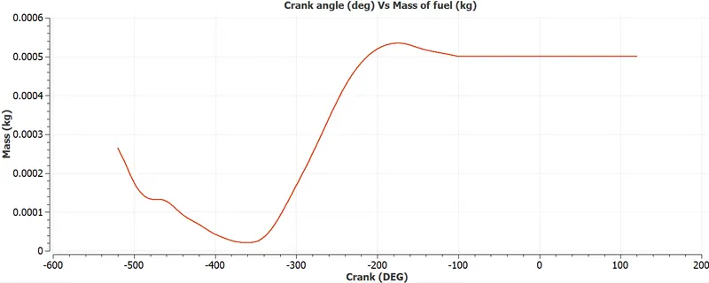
From the above plot, mass of air in kg can be 0.000534 approx (excluding fuel particles).
Therefore Va= 0.00045 m3
ηv = Va / Vt = 77.78%
Q4. Measure the air mass flow rate for this engine in kg/s.
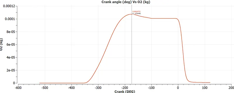
The maximum air quantity of 0.00010733kg occurs at CAD -174.442.
- RPM = 3000, RPS=3000/60=50
- Total air mass flow rate per second = 50*0.00010733= 0.0053665 kg/s
Q5.Why is the cell count varying during the simulation?
In converge, a baseline mesh is created either in uniform or non-uniform pattern along 3 axes. In this case, the cell count doesn't vary during the simulation. But most of the engineering problems like Port Fuel Injection, Shock wave simulation require dynamic or region-specific grids in order to capture the interesting physics accurately and to reduce the computational power requirements.
In this PFI simulation, two approaches are followed apart from the base grid being uniform along 3 axes with a cell size of 0.004m. The two approaches are Fixed embedding and Adaptive mesh refinement.
Fixed embedding: This scales down the cell size in the user-defined boundaries. This helps to capture the desirable physics accurately at a particular location and the rest of the regions where the physics behaves benignly are set with a baseline grid. In PFI simulation, a region around the spark plug is assigned with a fixed embedding grid.
Adaptive Mesh Refinement: This scales down the cell size based on the below expression;

- This is applied to the Cylinder region, Intake ports 1 and 2 of PFI where the gradients of temperature and velocity are high.
- A velocity and temperature-based AMR is applied with a Sub-grid scale embedding level of 3 and a criterion is set to be 2.5K difference with respect to temperature curvature (
 ) and 1m/s with respect to velocity.
 - Velocity-based AMR is applied permanently whereas Temperature based AMR is applied for a specific crank angle period.
The above two techniques cause cell count variation during the simulation.
Q6. In a real engine, valves are in contact with the cylinder head but while running simulation, there is a small gap. Why? What happens if this gap is big?
In CONVERGE, the intersection of surface triangles is not allowed and causes an error. In order to prevent the intersection, a small gap is provided in the simulation geometry. Instead, CONVERGE creates disconnect triangles to close the gaps (and thus cut off the flow) between regions. In the poppet valves of an engine, there is a concentric circle disconnection between the valve (a circular loop) and the valve seat (another circular loop). The figure below shows a cross-section of a valve and a valve seat in an engine. In this example, the purple lines represent boundaries assigned to region 1, while the red lines represent boundaries assigned to region 2.
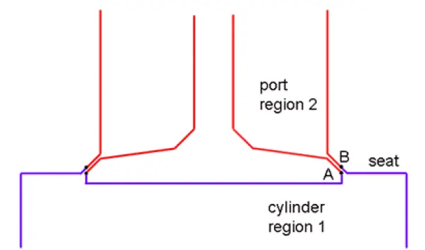
At the start of the simulation, CONVERGE will detect two circular loops where regions 1 and 2 meet: one loop around the base of the valve (point A in Figure 9.8) and one loop around the base of the valve seat (point B). Because there are two loops, CONVERGE will create a ring of disconnect triangles between the two loops (i.e., between the valve and the valve seat). You can activate or deactivate these disconnect triangles to control the flow between regions.
If the gap between regions exceeds, either heat transfer will not happen leading to several issues like knocking or there will be leakage of fuel and exhaust gas.
Q7. How many seconds does combustion last in this case?

- Duration = 240.199 deg
- RPM = 3000, RPS=3000/60=50
- Total angular rotation per second = 50*360deg=18000 deg
- Combustion Duration in seconds = 240.199/18000=0.01335 seconds
Questions based on DIESEL Engine:
Q1. What is an advantage of SECTOR Simulation?
The primary advantage of a SECTOR simulation is the reduction of computation time due to minimal geometry leading to a minimal number of cells and equations to be solved. The time taken for preprocessing the CAD is also reduced.
Q2. When will the sector approach not work?
SECTOR approach will not work in the following conditions;
- Open Cycle analysis-In this case valves are modeled and timing is set to initiate certain actions. This cannot be performed in a sector approach.
- Injectors in real-time scenarios are asymmetric. Hence open cycle analysis suits the best as it can be modeled as per the requirement. In sector simulation, this is set to be symmetric by default.
Q3. How to choose Start Crank Angle (SCA) and End Crank Angle (ECA) for a sector simulation?
Start Crank Angle has to be the beginning of Compression stroke and End Crank Angle has to be the end of the Expansion stroke.
Q4. Can we convert the PFI case into a SECTOR case? Explain your answer?
No, the PFI case cannot be converted into a SECTOR case because of the following reasons.
Sector simulation simulates a portion of piston profile and does not take other considerations like valve profiles, injectors, etc.
Even if injectors are added they will not be symmetric and extrapolating the profile of a sector may not lead to an accurate result.