Week 6 - CHT Analysis on a Graphics card
The Geometry
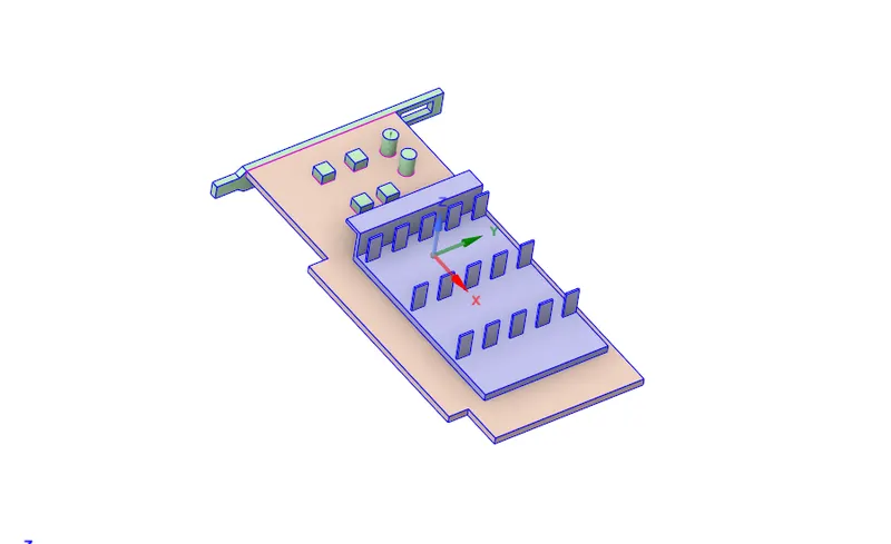
This is the geometry of the graphics card which we are going to simulate. It contains three main parts
the
Base Board ( baseplate)
Fin
Processor
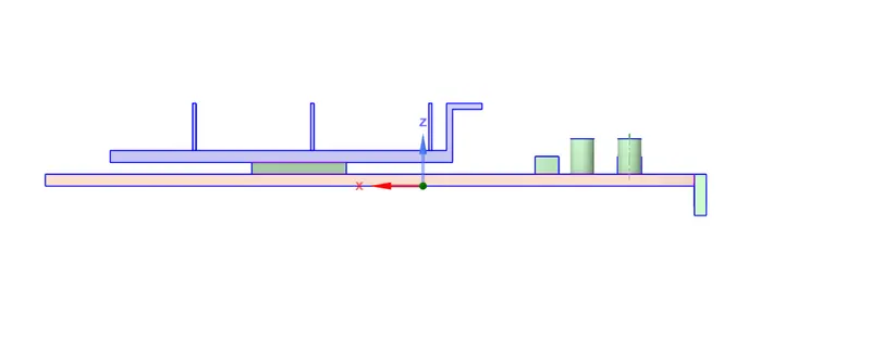
The Side view of the Graphics card, as you can see the green part showing is the processor and the blue part at the top is the fin, used to dissipate the heat.
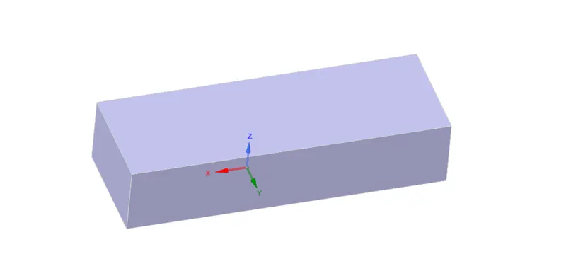
For simulation purposes, we enclosed the graphics card in a box.
Meshing
Case 1
For case 1, the mesh sizing is as follows
Outer enclosure - 5mm
Baseboard - 2mm
Fin - 2mm
Processor - 1mm
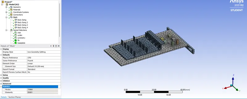
Total number of elements = 83801

As you can see the element quality is good.
Fluent
In fluent, firstly enable the energy option
The Viscous model we use is K-omega
Materials
Processor - Titanium
Fin - Copper
Baseplate - Aluminium
The Inlet velocity is 1m/s.
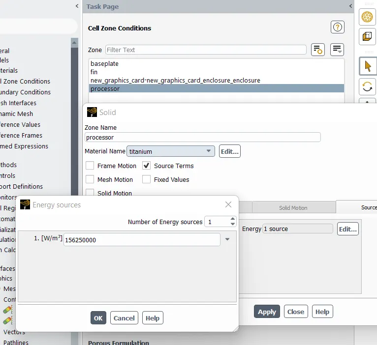
In Cell zone we enable source term for the processor and the value fro the Energy source is 156250000 w/m^3.
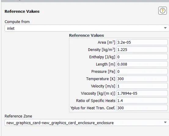
Also the reference values are as follows
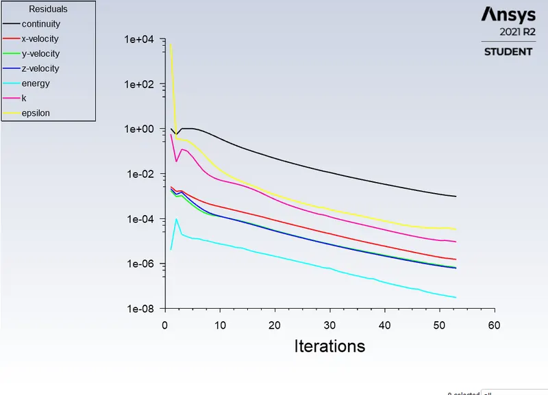
Now we run the simulation for 200 Iterations
Results
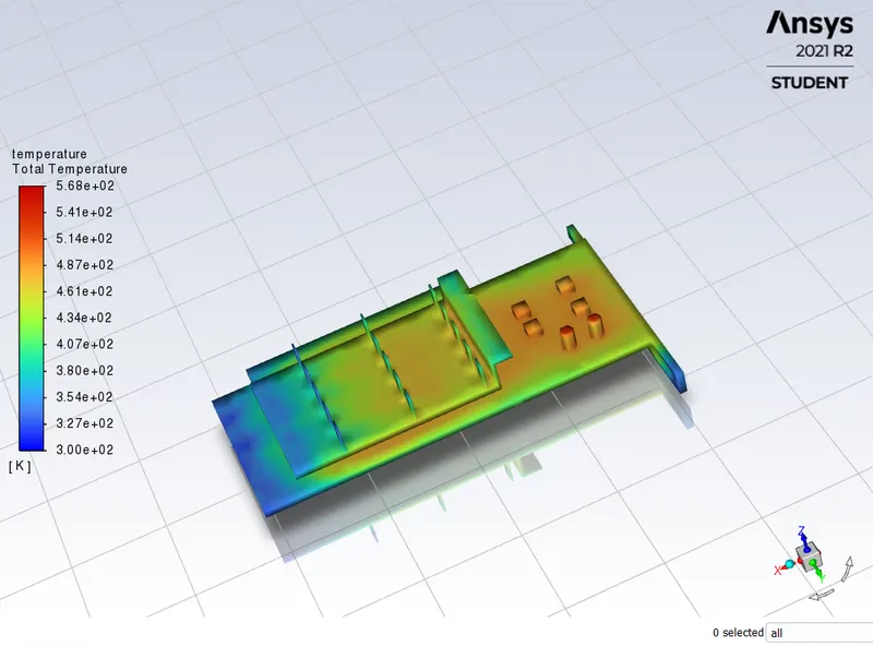
The Total temperature contour of the graphics card is.
Scaled residuals
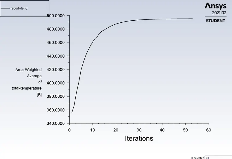
The area weighted average calculated as..

Ansys Post
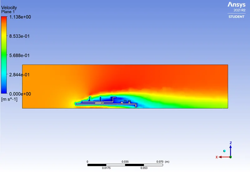
The Velocity plot
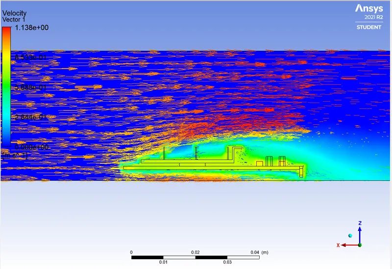
Velocity vector plot
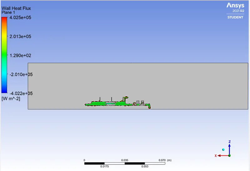
The Wall Heat Flux
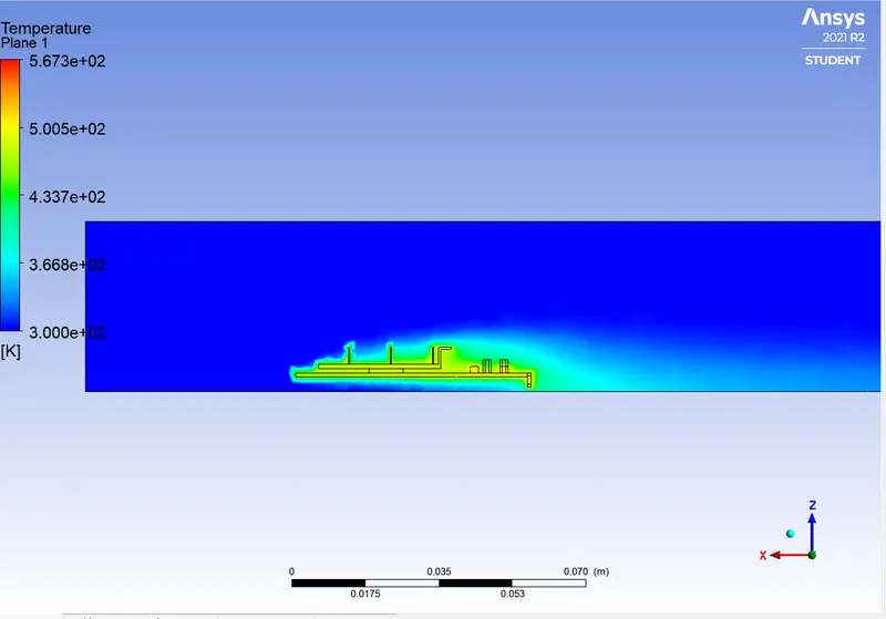
Temperature Contour
CASE 2
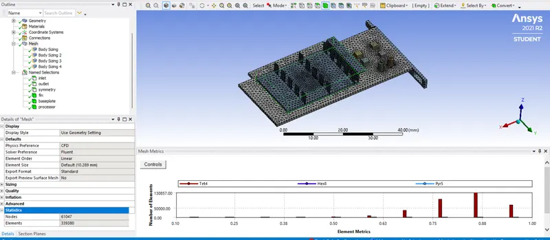
Here we refined the geometry by reducing the elemenst size
Outer enclosure = 3mm
Baseplate = 1mm
Fin = 1mm
Processor = 0.5mm
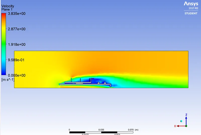
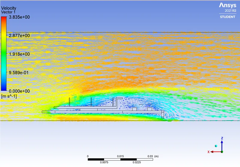
The Inlet velocity is changed to 3m/s
Results
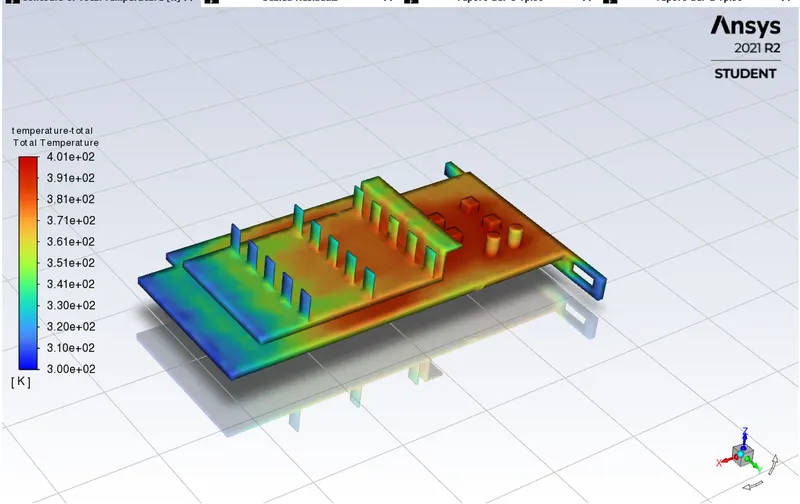
The Total temperature contour
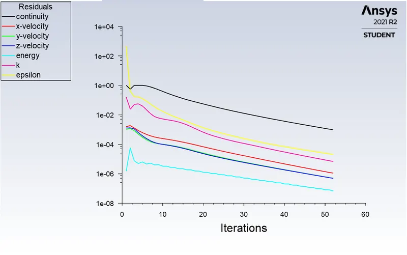
Scaled Residuals
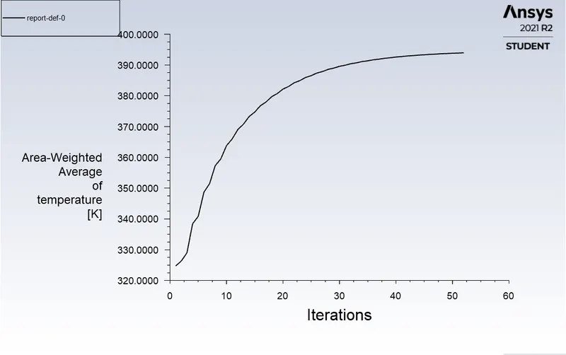
Area-weighted average of temperature
Ansys Post
Velocity contour
Velocity vector
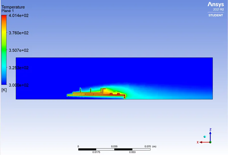
Temperature contour
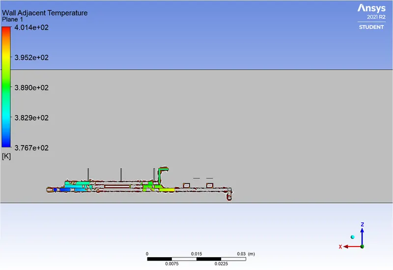
Wall Adjacent Temperature
CASE 3
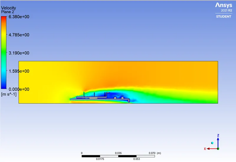
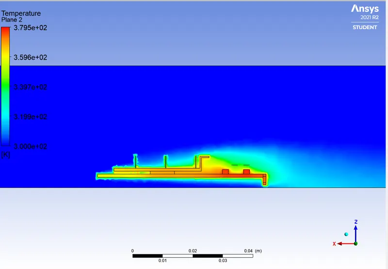
In case 3, we have increased the air flow velocity to 5 m/s, but the mesh size is same as the previos case.
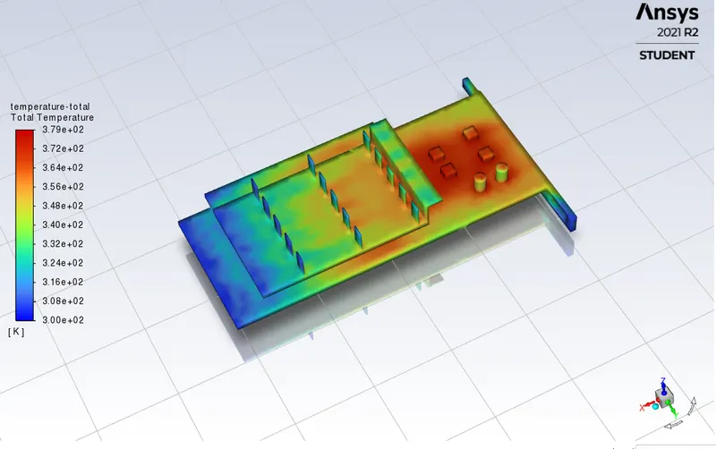
The total temperature contour
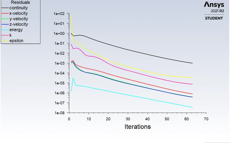
The scaled residuals
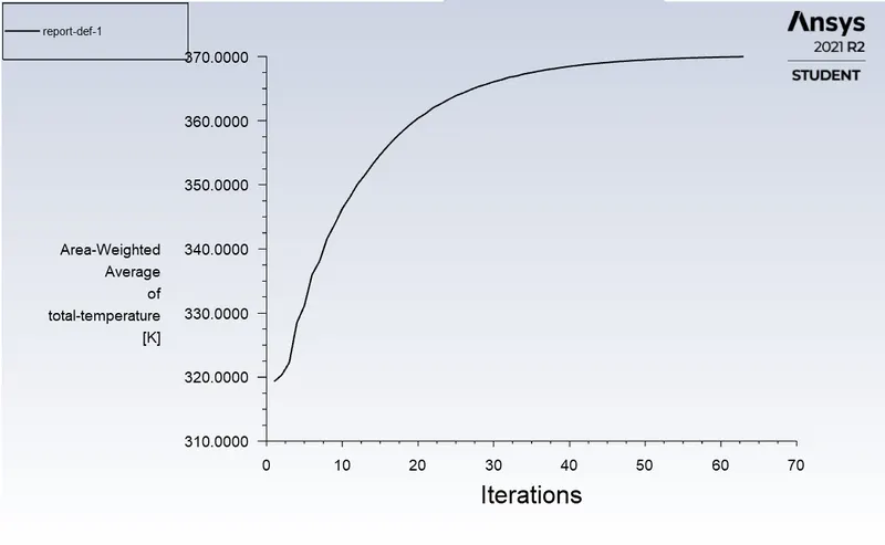
The Area-weighted average of temperature.
Ansys Post
Velocity Contour
The temperature contour
Conclusion
As we decrease the mesh size, the accuracy of heat dussipation incresases
The hotspot of the graphics card is the main processor which has the maximum temperature