Week 11.1: Turbo Charger Simulation Project
Title: Turbo Charger Simulation
Aim:
- To run simulation for 3 different pressure ratios of 2, 2.5 and 3.
- To increase the END TIME of the simulation and check if convergence is achieved for the angular velocity of the Turbine.
Theory
A turbocharger (technically a turbosupercharger), is a turbine-driven, force induction device that increases an IC engines power output by forcing extra compressed air into the combustion chamber. This improvement over a naturally aspirated engines power output is because the compressor can force more air—and proportionately more fuel—into the combustion chamber than atmospheric pressure alone.
Manufacturers commonly use turbochargers in trucks, cars, trains, aircraft, and construction-equipment engines. They are most often used with otto cycle and diesel cycle IC engines.
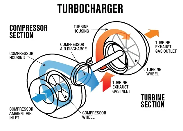
Figure: Turbocharger
Geometry:
Case-set up (2 bar pressure)
- Gas simulation (Air)
Run parameters
- Simulation time parameters
- Boundary conditions
Outlet
Turbine wheel
Results
- Rotational velocity (all 3 cases)
As can be seen from above plot, with increase in pressure of compressed air, required rotational speed can be achived quickly.
- Rotational acceleration (all 3 cases)
- Temperature at inlet and outlet
- Density at inlet and outlet
- Velocity at inlet and outlet (2 bar)
At inlet, velocity is more due to high energy possesed by air at inlet.
- Velocity at inlet ( all 3 cases)
- Density at inlet (all 3 cases)
Conclusion
All 3 cases simulated successfully, FSI based simulation is carried out successfully