Week 4 - 2D Meshing for Sheet Metal
Week 4 - 2D Meshing for Sheet Metal
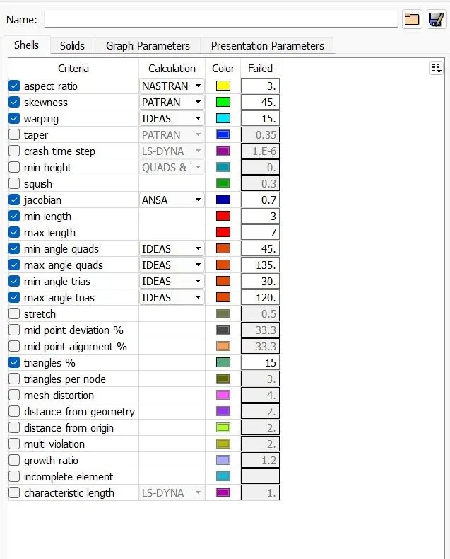
For the given CCB CAD model, Check for the Geometry cleanup (if required), Take the mid surface, and Mesh it with the below 2D element Quality criteria.
The Below given is the CAD geometry of a CCB, which we need to be meshed as per the requirement.
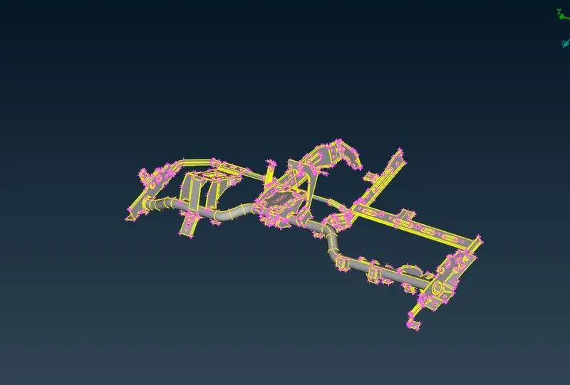
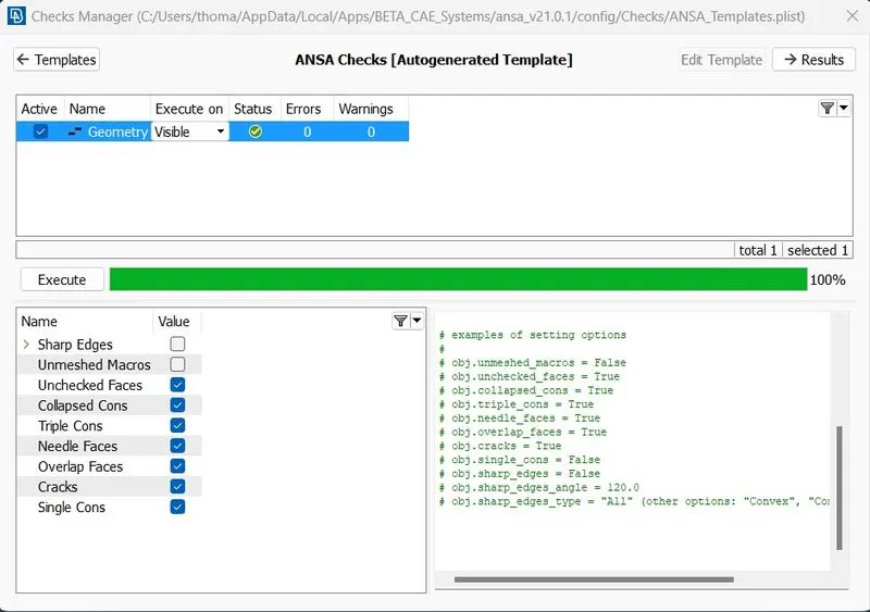
First we need to do a geometry check and fix the errors
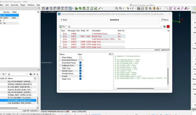
I have done a face delete on errors like these needle faces.
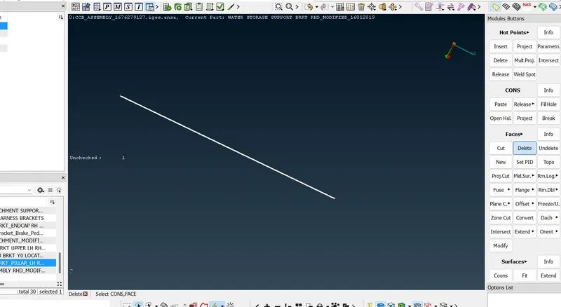
As there were many errors and we had done a topo cleanup on each individual part and the error is fixed.
Mid Surface
The next step is to create a mid-surface for the geometry.
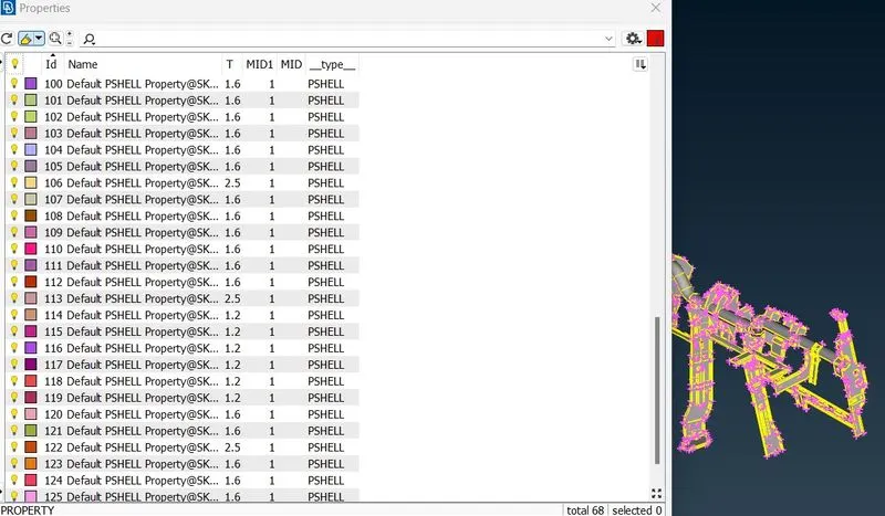
For that under the Faces tab, > Mid.Surface > Skin and drag select the entire geometry and midplane is assigned for each individual plane.
As we enabled the option to create new PID for each skin we are making, each new PIDs are generated while making the Mid surface.
Next we need to assign the quality criteria as per the question, before starting the meshing.
MESHING
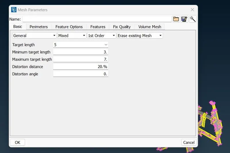
Now, we need to start the meshing,
for that we given a perimeter length as 5mm.
In the mesh generation > selected the Best mesh type.
Therefore a basin automated mesh is generated.
As this is a basic mesh so thier will be so many errors, so we used Shell Mesh > Reconstruction and Shell Mesh > Smooth tools to fix the mesh as per the quality.
Also, we used Split elements to adjust the size of each individual mesh.
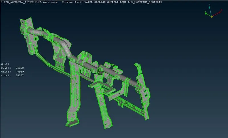
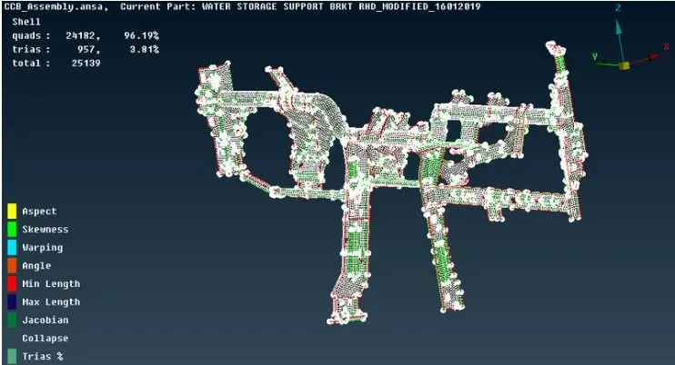
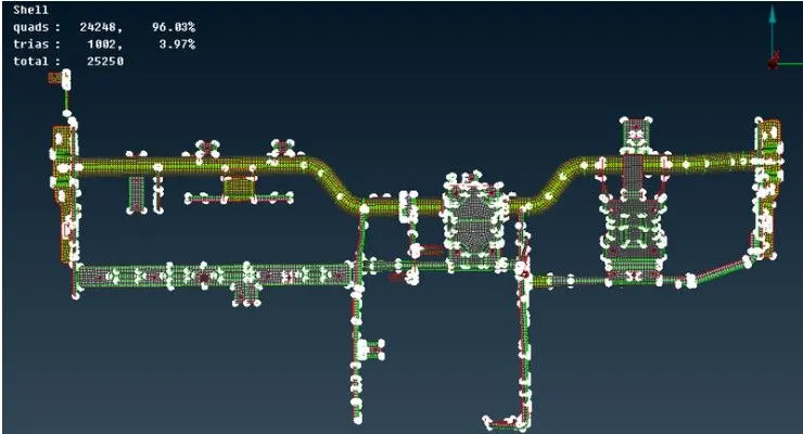
Result
Checked for the Geometrical errors & taken mid-surface for C.C.B Assembly and Meshed with the given Element quality Criteria for the given Component.