Week 1: Channel flow simulation using CONVERGE CFD
1. For this challenge, we will be setting up a channel flow tutorial.
2. As you watch these videos, setup the case in CONVERGE
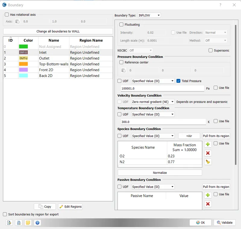
3. Make sure the inlet pressure and initial pressure are the same.
4. Once you have the base setup ready, run the case for three different base mesh sizes
i.e You need to run 3 simulations and compare the results between all the 3 simulations.
3 different base mesh sizes are,
- dx = 2e-4m, dy = 2e-4m, dz = 2e-4m
- dx = 1.5e-4m, dy = 1.5e-4m, dz = 1.5e-4m
- dx = 1.0e-4m, dy = 1.0e-4m, dz = 1.0e-4m (If this is too much for your PC, use 1.2e-4m)
Answer
Here, we simulated air flow through a 2D rectangular box-like shape using Converge and the following results were obtained.
Here is a complete step showing the entire process of this simulation setup.
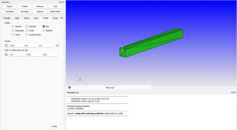
First, we need to create our geometry. The rectangular box is made with the following dimensions as shown in the image.
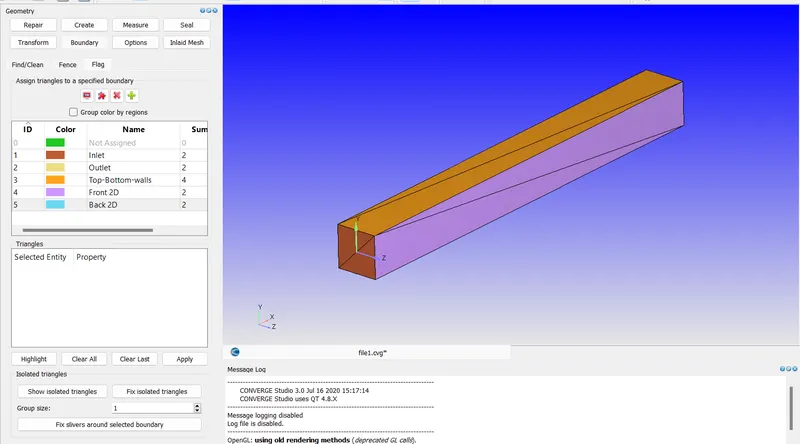
Now, the next step is to define each face of the geometry with an appropriate name.
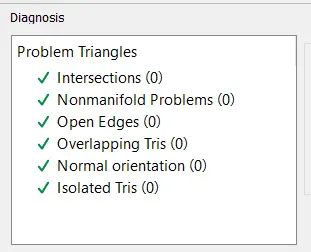
Then we had done a small diagnostic check-up for any kind of errors during the geometry creation.
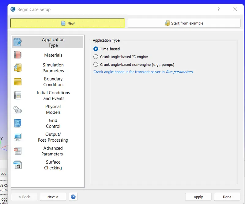
Now, here we started to define the case-setup tree.
Here we uses a Time-based Problem.
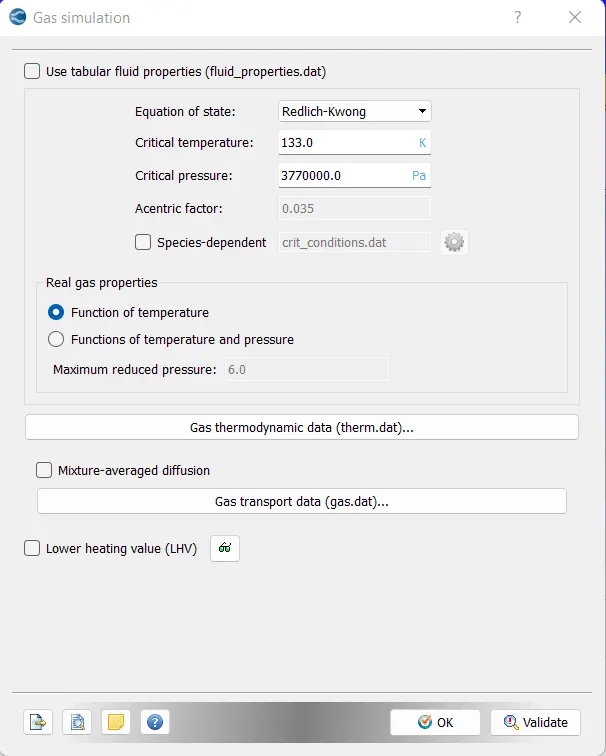
As this is a basic problem, so we make this option, which is the Gas simulation as default.
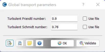
Similarly, we make the Global transport parameters also with default values.
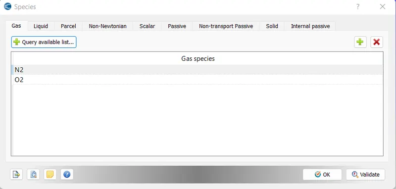
Now, we need to add the elements which we are considering on this problem, which is O2 and N2.
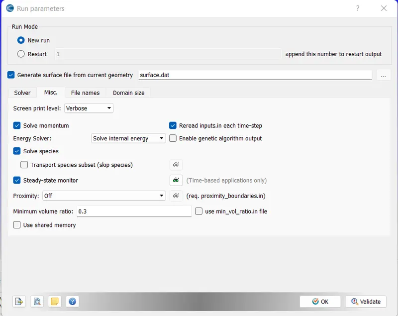
Now, the Run parameters are to be set.
Solver - Steady-state solver
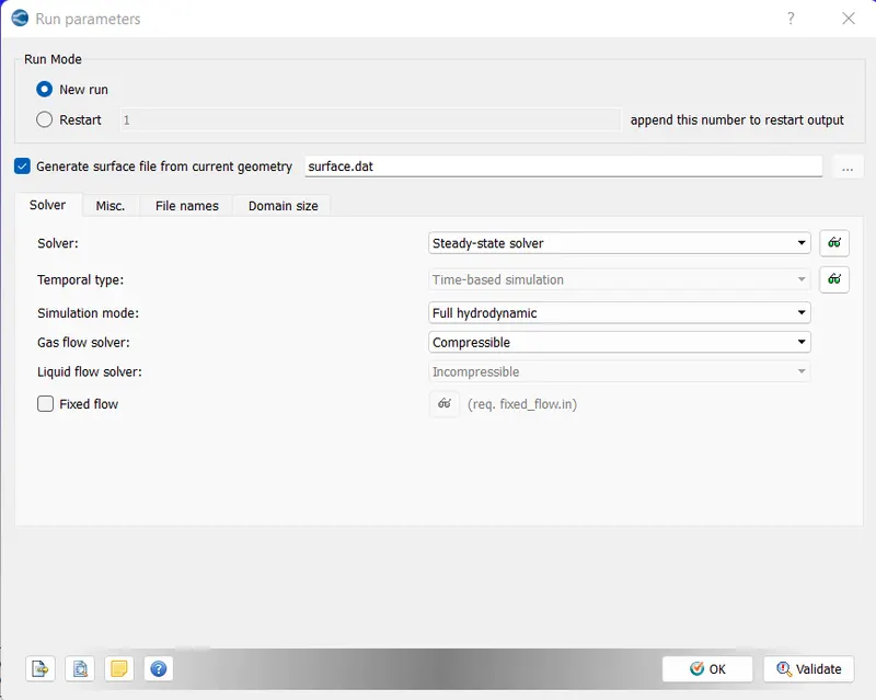
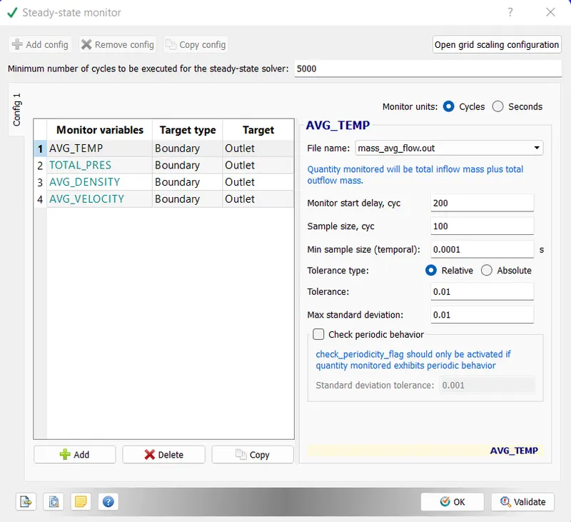
Here, enable the Steady-state monitor and un check the Shared memory.
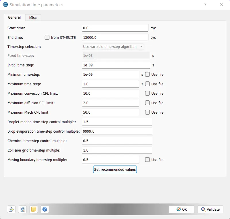
The simulation parameters is to be set as follows.
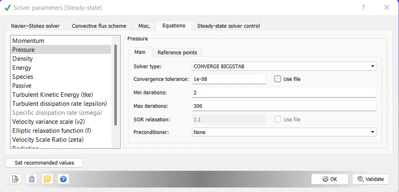
The solver parameter
Now, the most important part is setting up the Boundary conditions.
Inlet.
Outlet
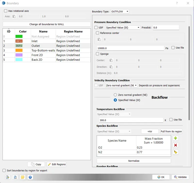
Top-Bottom walls
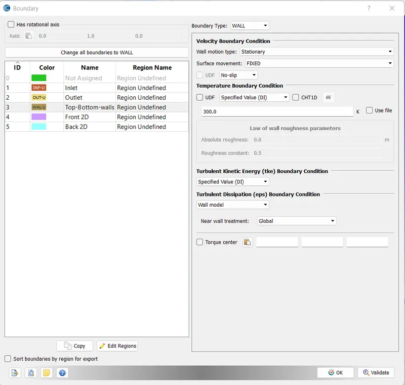
and make TWO_D for Front_2D and Back_2D
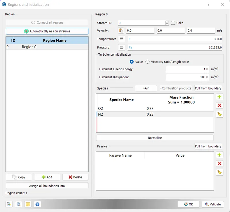
Regions and Initialization
Steady-state monitor.
Setting up the Mesh.
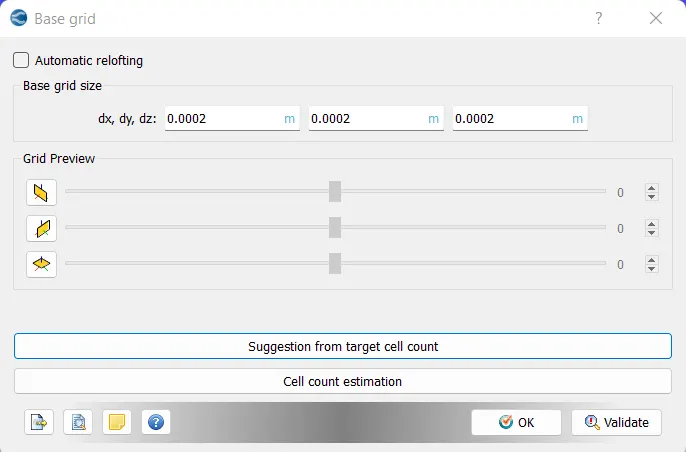
here, as of Case 1 in the question, we use dx = 2e-4m, dy = 2e-4m, dz = 2e-4m
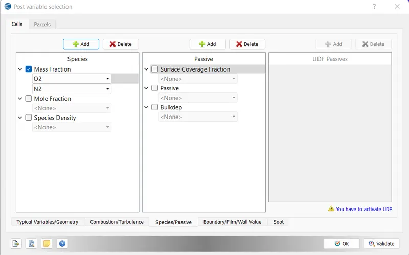
Post variable selection
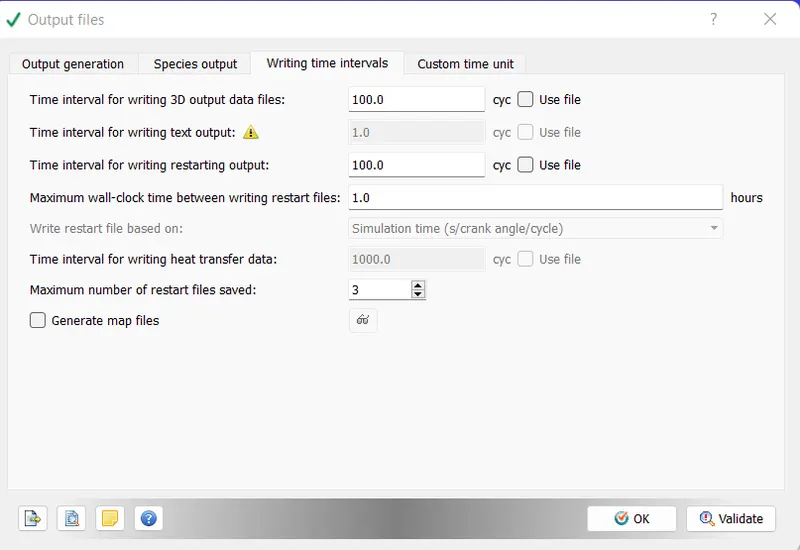
Output Files
and finally, it's time to export the saved case setup files.
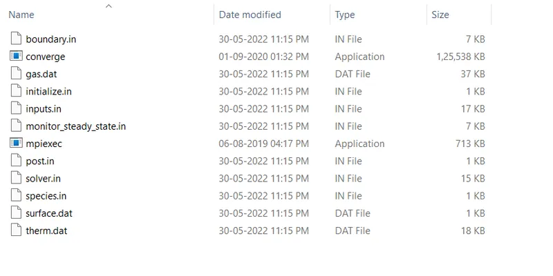
We now, export all the worked files to a created folder within the PC.
and here it exports 10 files to it.
Now, for the simulation purpose, we copied 2 additional files from the C drive to this folder, namely, converges.exe and mpiexec.exe.
Now, it's time to run the simulation.
First, we navigate the Cygwin to the output folder where we have saved all the worked files.
now we enter the following command to run the simulation.
"mpiexec.exe -n 4 cnverge.exe restricted </dev/null> logfile &"
and click enter, then the simulation starts to run.
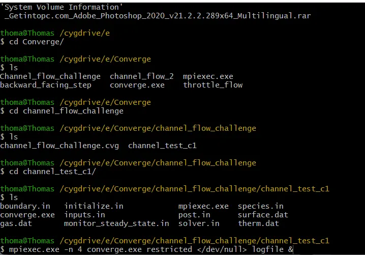
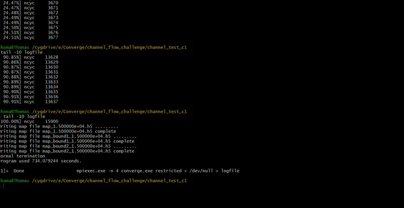
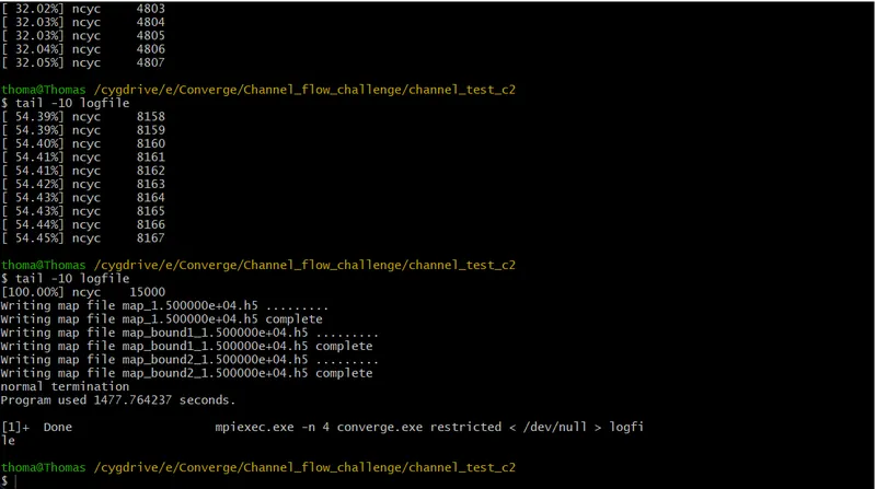
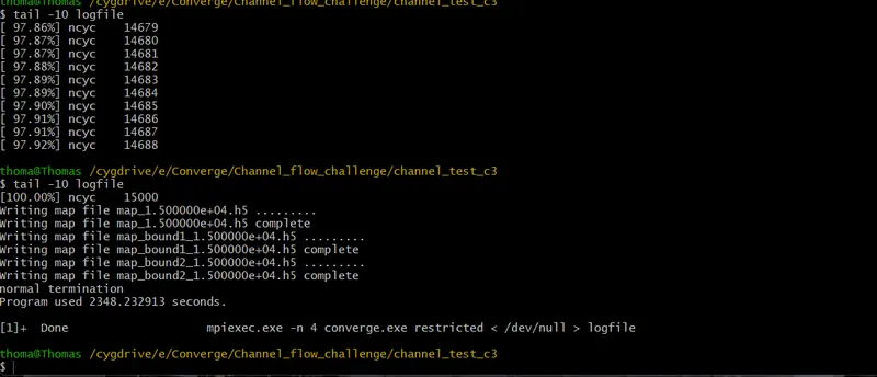
we can watch the simulation progress by using the command, tail -10 logfile.
We can see that the simulation ran successfully without any errors.
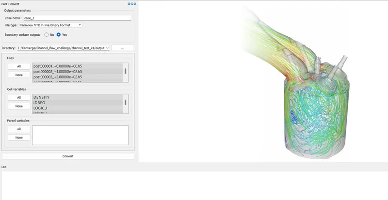
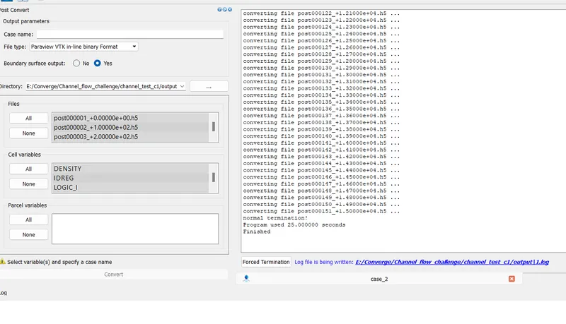
Now, we need to convert the binary files made from simulation to ParaView readable format. For this, we open converge and convert the file as follows.
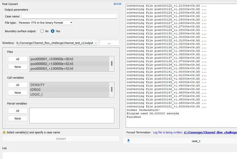
The files have been successfully converted.
Now, to post-process the simulation or the results we use a software called ParaView.
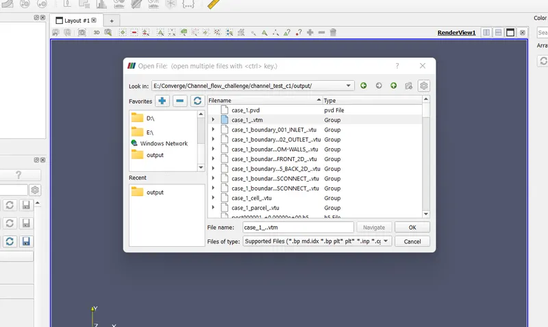
Here, we need to open the .vtm files (group), and click apply.
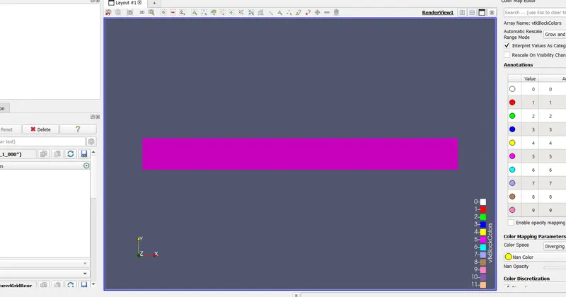
The 2D geometry has been successfully loaded.
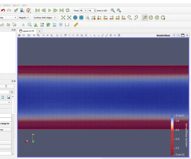
Results.
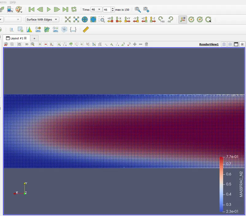
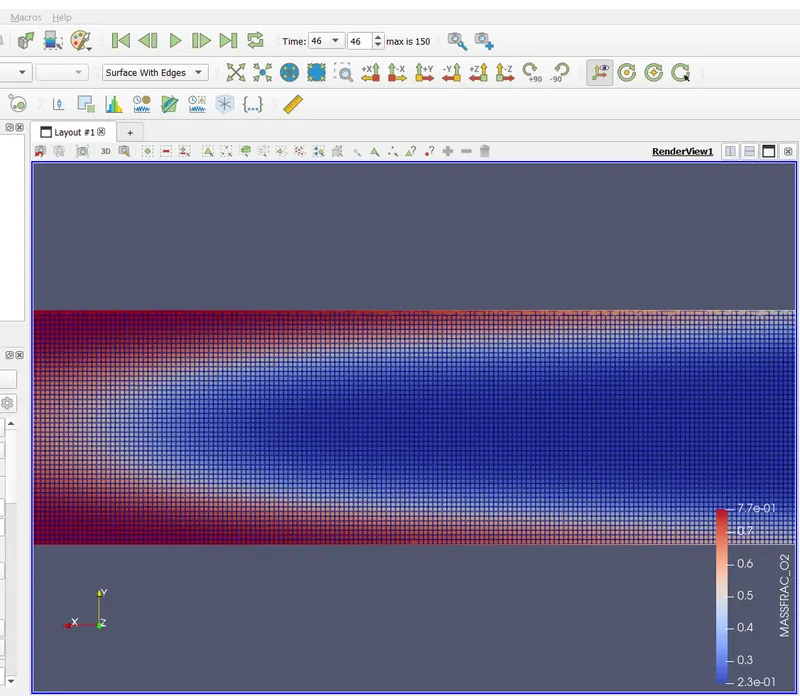
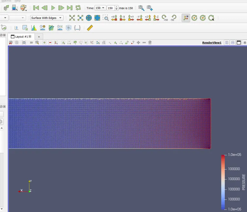
***for the first two cases, i have accidentally used the Surface with mesh option, so in order to clearly view the results I need to zoom in the image, thus a zoomed image.***
Velocity
Mass fraction of N2
Mass fraction of O2
pressure
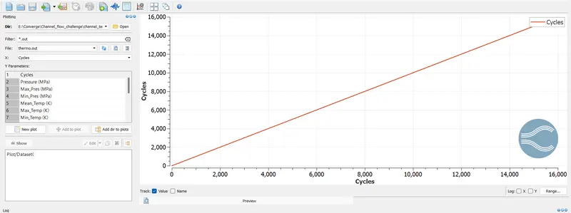
Line Graph
Cycles
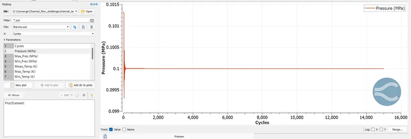
Pressure
Mean Temperature
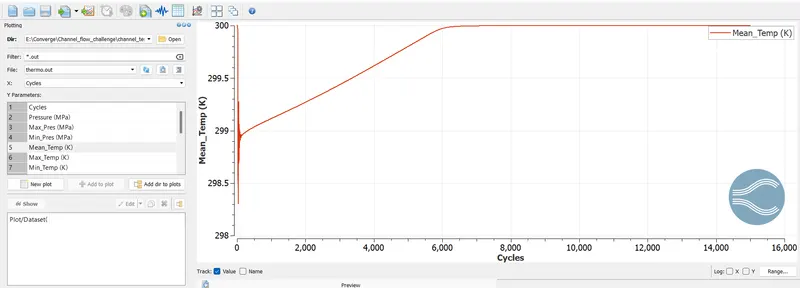
************************************* CASE 2 ********************************************
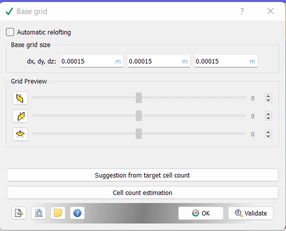
- dx = 1.5e-4m, dy = 1.5e-4m, dz = 1.5e-4m
We had changed the base grid option according to the question.
Running the simulation.
Conversion
Results
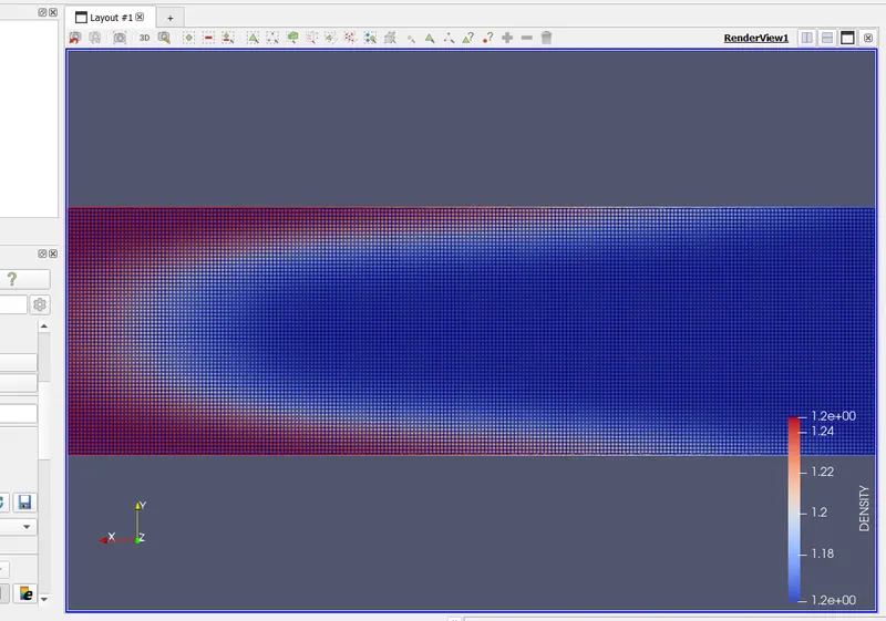
Density
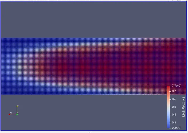
Mass fraction of N2
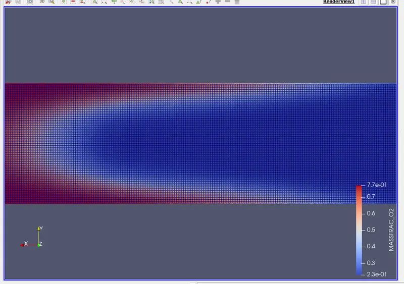
Mass fraction of O2
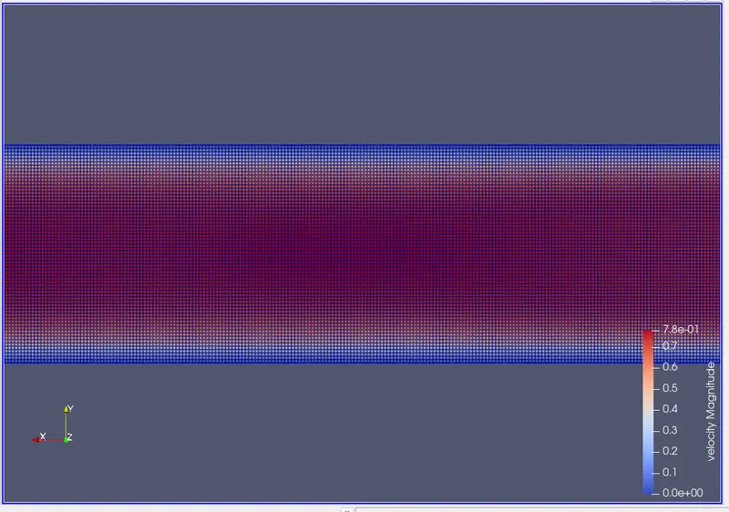
velocity
Line Graph Plotting
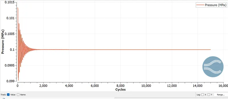
Pressure
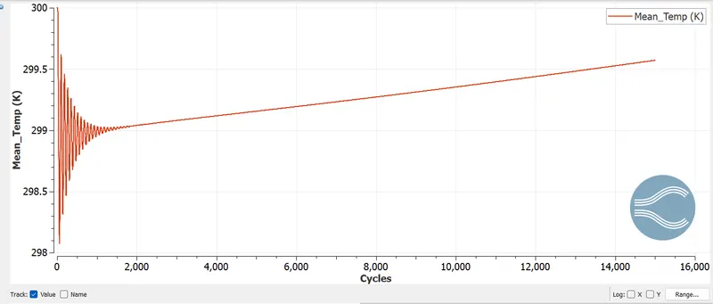
Mean temperature
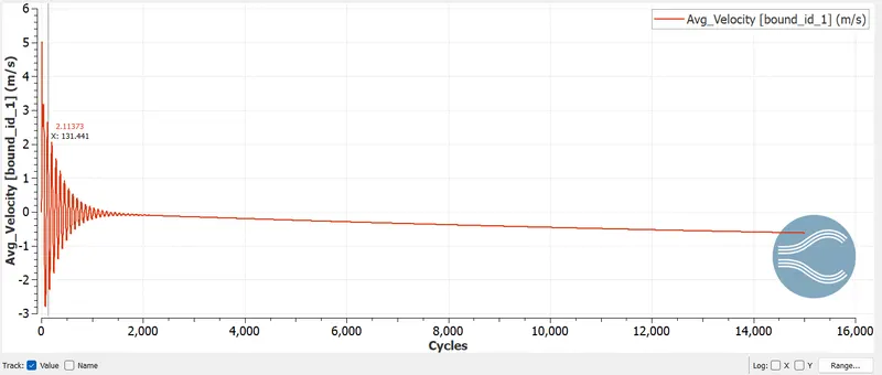
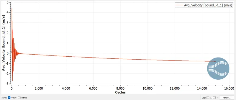
Average Velocity
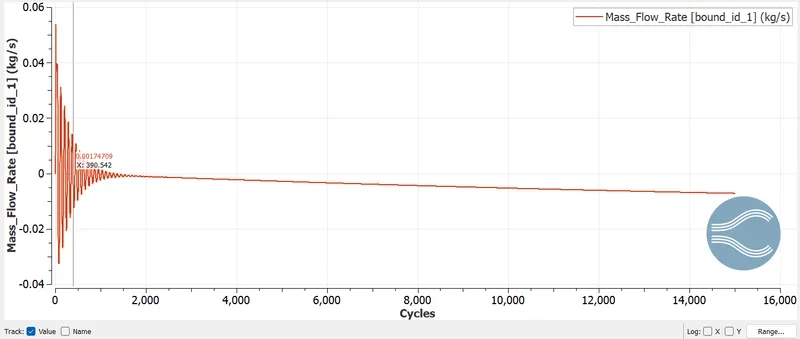
Mass flow rate
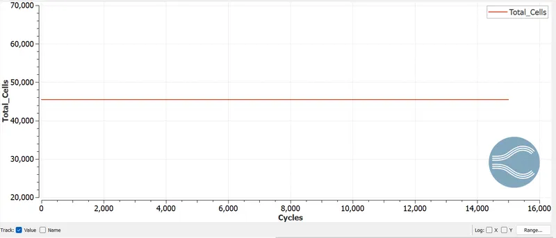
Cell Count
************************************* CASE 3 ********************************************
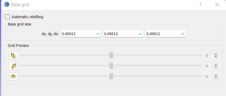
Cell size - dx = 1.2e-4m, dy = 1.2e-4m, dz = 1.2e-4m
Setting up the mesh size as per question.
Running simulation on CYGWIN.
RESULTS
Pressure

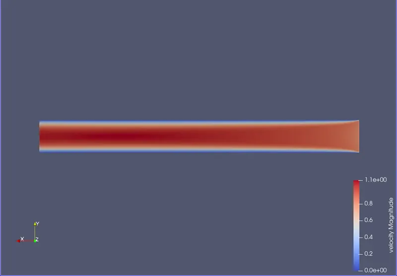
Velocity
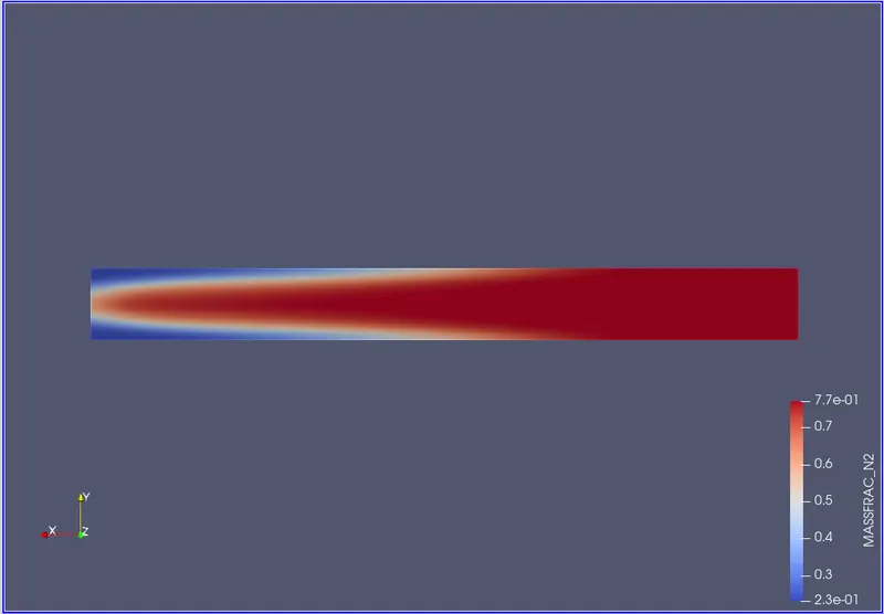
Mass fraction of N2
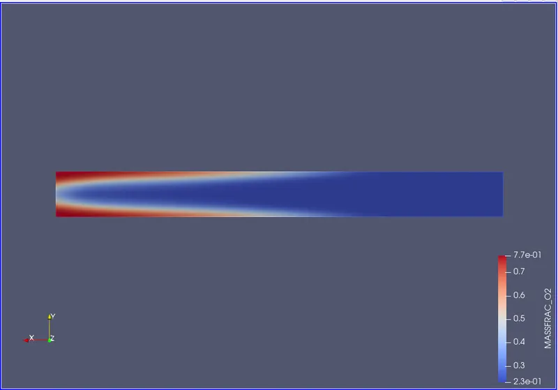
Mass fraction of O2
Line Plotting
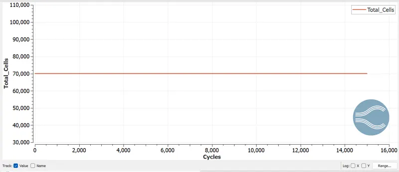
Total Cell count
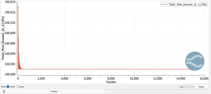
Total Pressure
Avg Velocity
END