Week 2 Challenge : Surface meshing on a Pressure valve
AIM
For the given model, check for the geometrical errors and perform Topology cleanup accordingly. Set three different target lengths as three different cases and mesh the model.
- Target length = 1mm, 3 mm and 5 mm (i.e. 3 cases)
- Element type = Tria
Apply any one target length from the above at a time for the entire model as One case. Submit 3 different models for 3 cases.
Write a detailed report on your meshing process and also mention which case is giving good results along with the reason.
Geometry
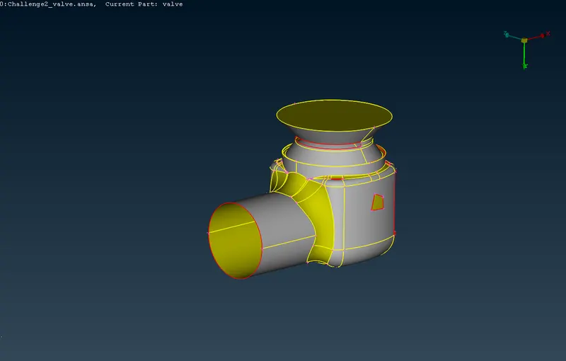
The Geometry which we are going to deal with today is as follows. This is a 3D thin model of a pressure valve.
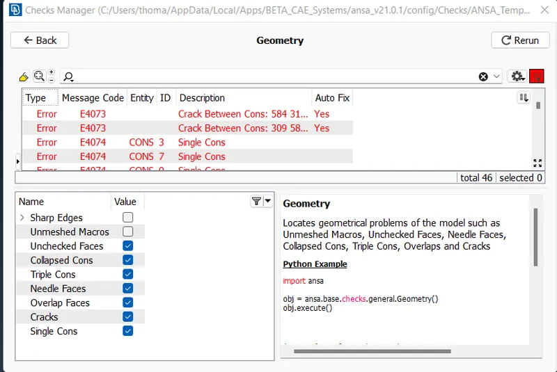
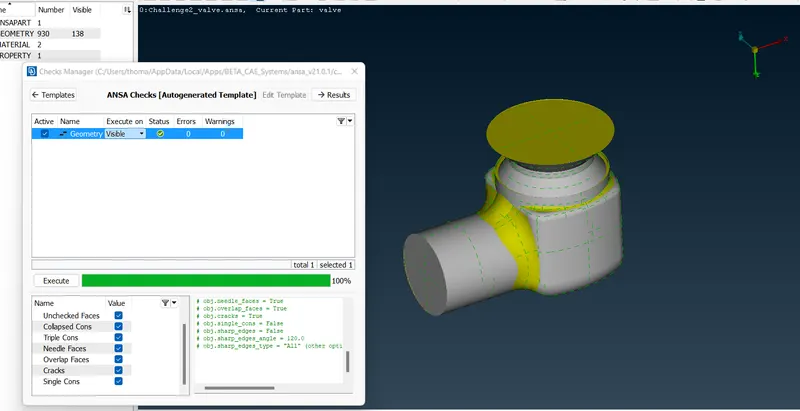
First, we need to check the geometry for any kind of errors and we came to see a few errors with this model. Errors like Single cons, Double Cons, Cracks etc.
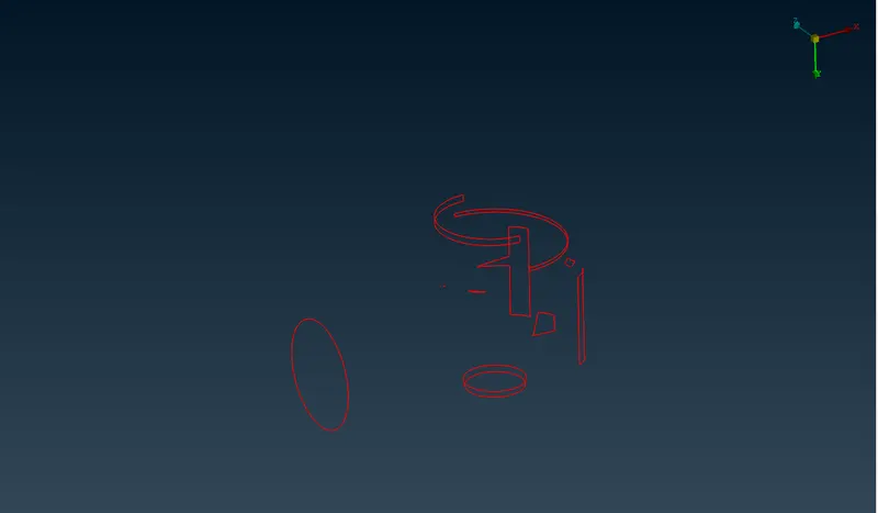
When Looking on the wire frame view, these are the patches that needs to be filled.
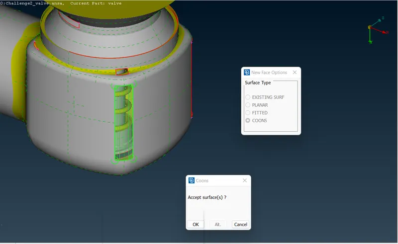
Now, we started to fill these patches using a face tool.
Every holes and patches are being filled and the geometry is in perfect condition
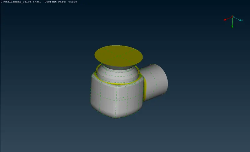
after that, we again checked for the quality again and we found the the geometry is 100% ok.
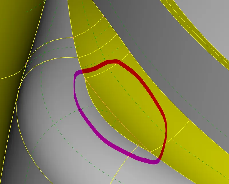
Now, we need to remove the lines joining the narrow parts because, when we assign a cell size more than the size of the part, it may show up some error. So these lines which makes narrow parts or cells should be removed using cut option.
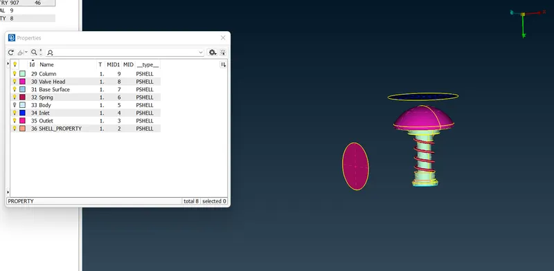
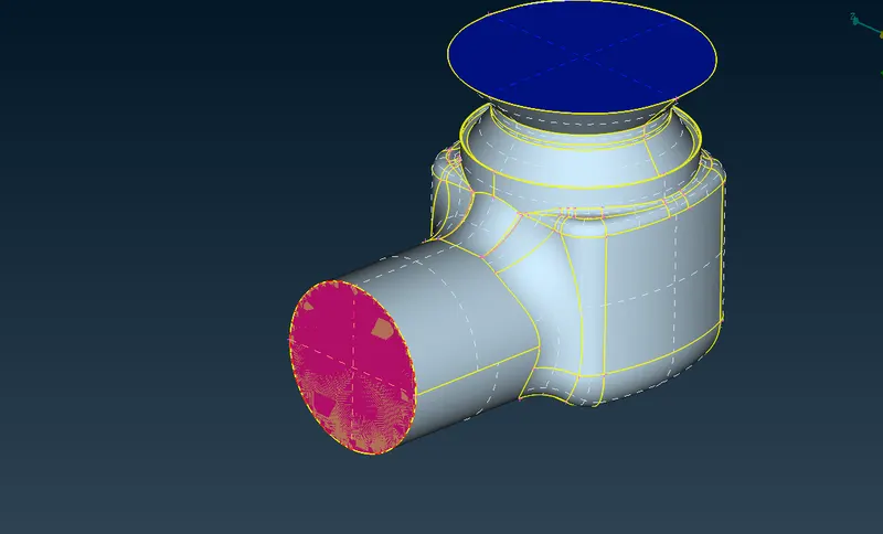
Now, the next step is to insert PIDs. PIDs are to assign the faces.
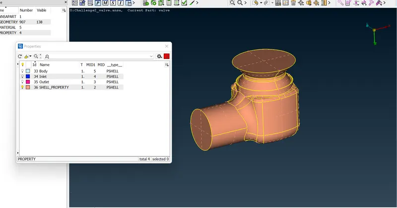
Every PID is being assigned.
Now is the time for Meshing.
CASE 1
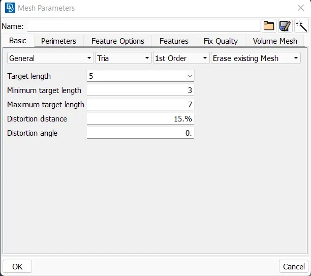
Mesh Length - 5 mm
Minimum Length - 3mm
Maximum Length - 7mm
First, we set values for the perimeters and Macros
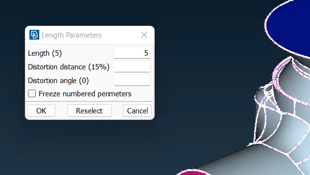
Defining Mesh Parameter
Mesh Quality
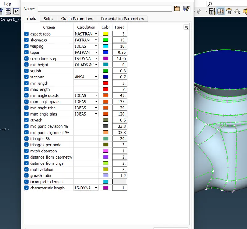
Using the spot mesh algorithm, we obtained the mesh on the geometry of size 5 mm
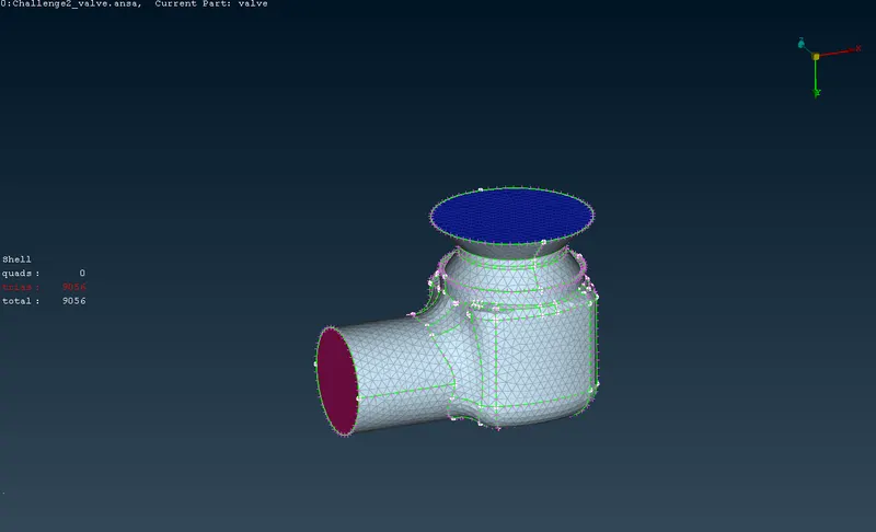
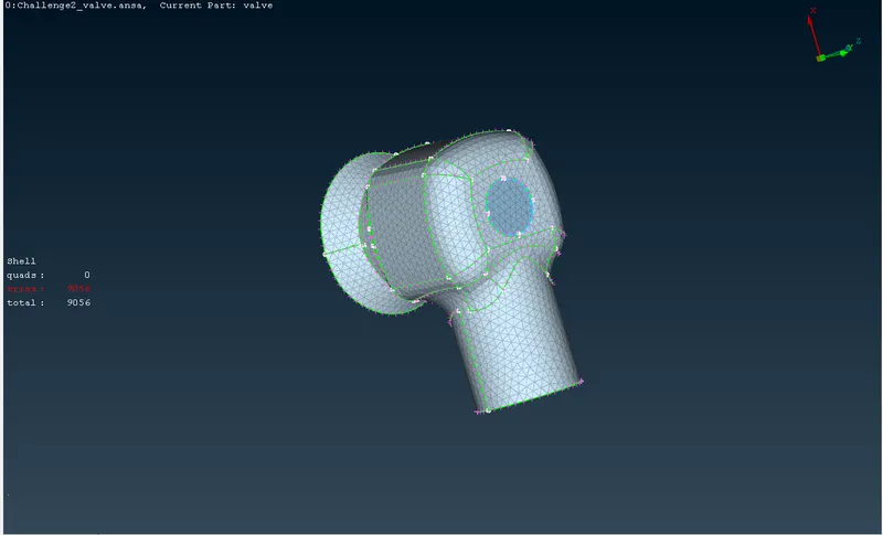
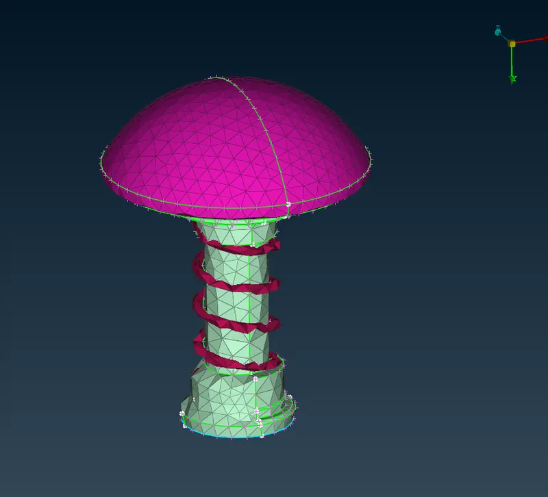
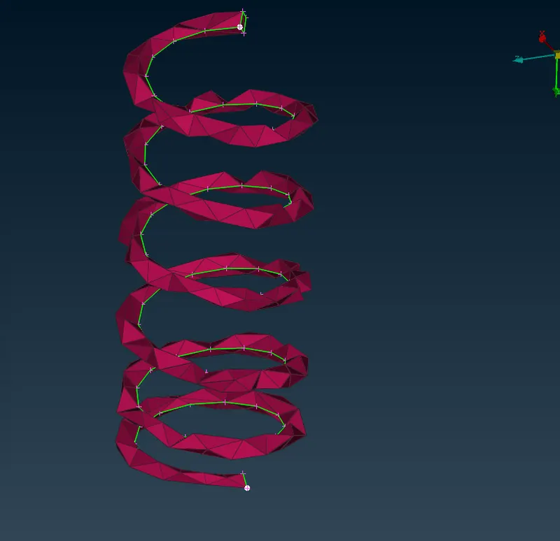
For this 5mm Mesh we can see that the surface is not well defined, such that the surface of the springs are like 2D geometry, And, many errors at the edges of the valve head and every geometry.
CASE 2
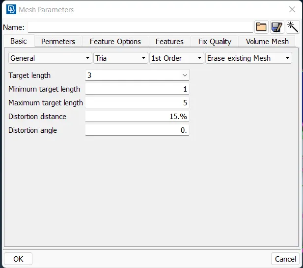
Mesh Length - 3mm
Minimum Length - 1mm
Maximum Length - 5mm
Defining Parameters and Macros
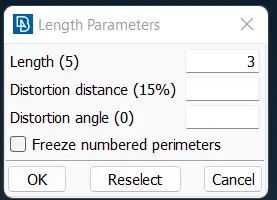
Defining Mesh Parameter
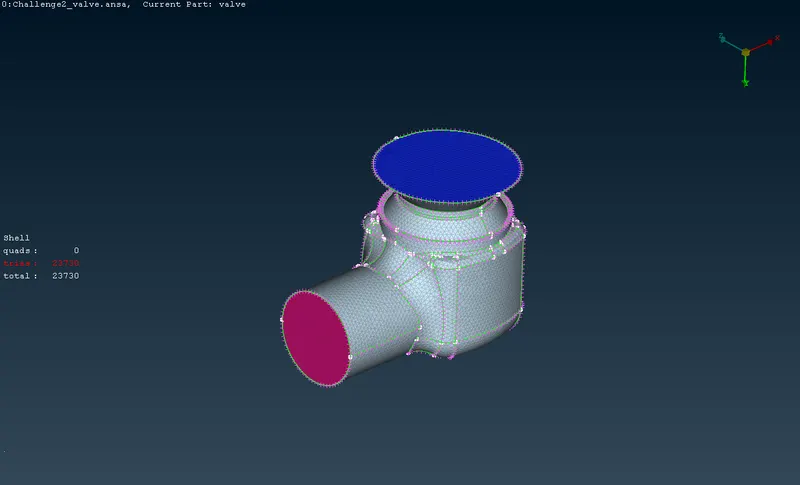
Meshing the Entire geometry using spot meshing algorithm
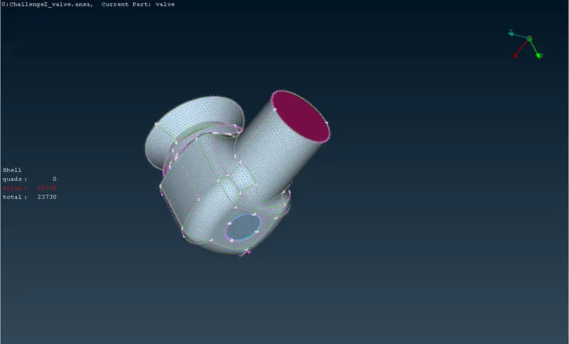
Meshing the internal Valve head
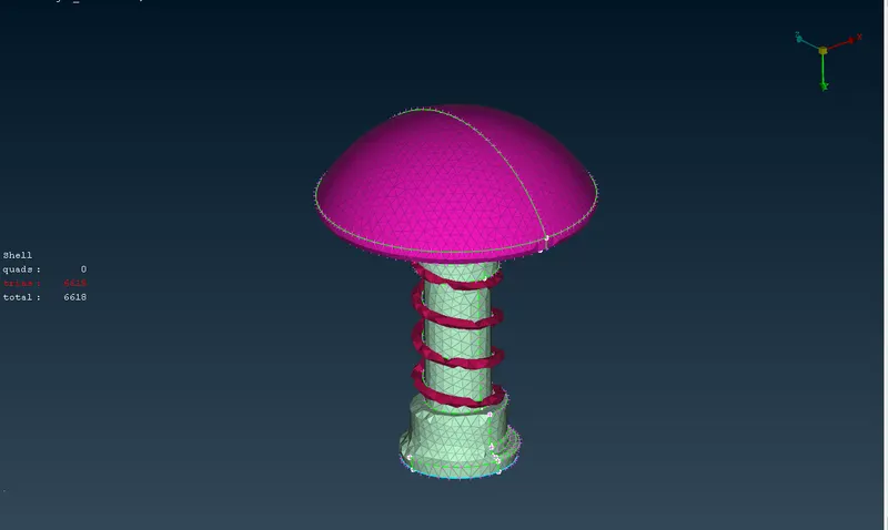
Springs
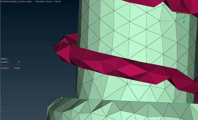
Here the Meshing is done for 3 mm, which is a little more refined than in the previous case. Even if the geometry is refined more than in the previous case, we can see the edges are not smooth enough to do a good simulation, so we need to do a higher refinement.
CASE 3
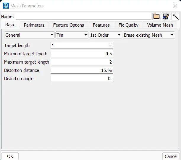
Mesh Length - 1mm
Minimum Length - 0.5mm
Maximum Length - 2mm
Defining the Perimeter and Macros
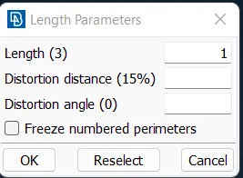
Defining the Mesh parameter and quality
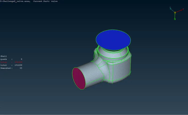
The Meshed Geometry
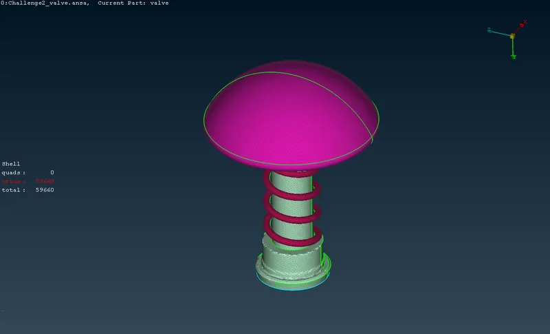
The Valve Head
The edges!
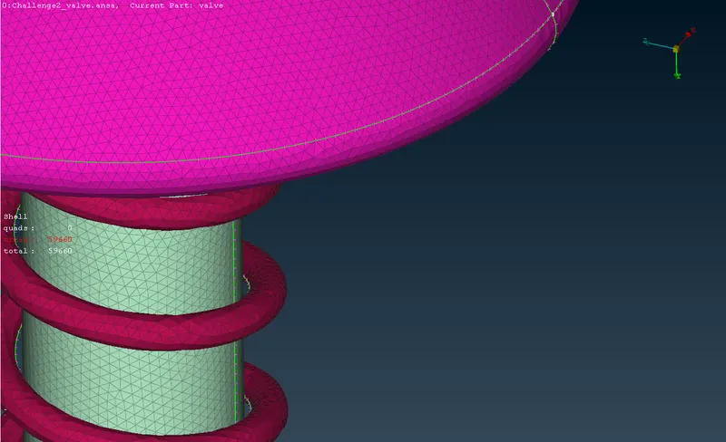
Here the mesh is done for 1mm size and we can see that the geometry is well defined and have a good surface finish. Also, the quality of this meshing is so finer that we can do high levels of simulation.