Week 9 - Mini project - Flow over an Airfoil
Week 9 - Mini project - Flow over an Airfoil
You will have to calculate the following,
- Drag co-efficient Vs Angle of Attack
- Lift co-efficient vs Angle of Attack
- Compare the effect of turbulence models on the above two results.
- Make sure that the inlet Reynolds number is 200,000
- Make sure you do above calculations for the following angle of attacks,
- Angle of attack = 1º
- Angle of attack = 5º
- Angle of attack = 10º
- Angle of attack = 15º
Answer
Geometry Preparation
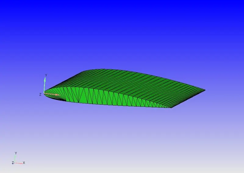
The geometry of the airfoil designed is NACA 2412 Airfoil. The prepration of the geometry is completelty same as that shown in the tutorial video.
The below picture is the extruded CAD model of the airfoil.
Now we have made a casing to the extruded airfoil geometry and finally the airfoil geometry is deleted or removed from it.
The outer casing represents the boundary inside which the simulation is happening.
The boundaries made for this simulation is
Inlet
Outlet
Left_Two_D
Right_Two_D
Symmetry
Wall
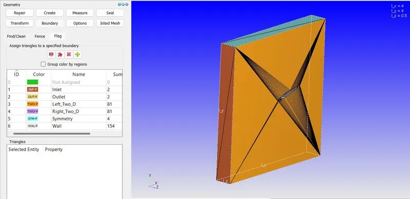
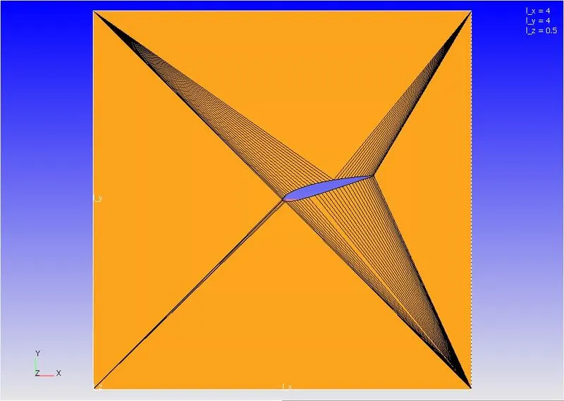
Side view of the geometry, in which the simulation is happening.
Case Setup
Now we need to set up all the cases for the simulation.
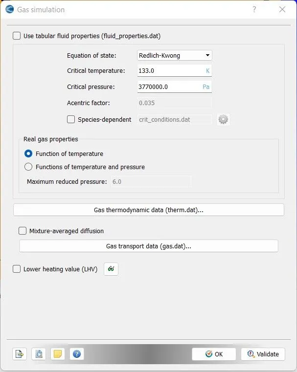
Gas Simulation, make this as default
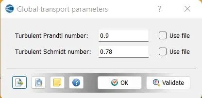
Global Transport Parameters - This also as default
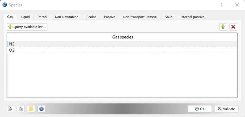
Species as N2 and O2
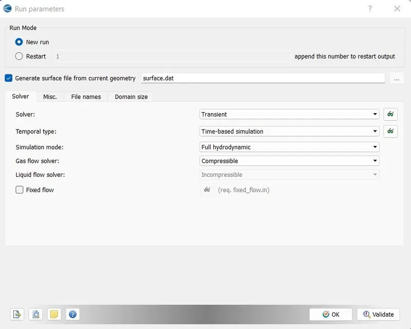
Run Parameters as this
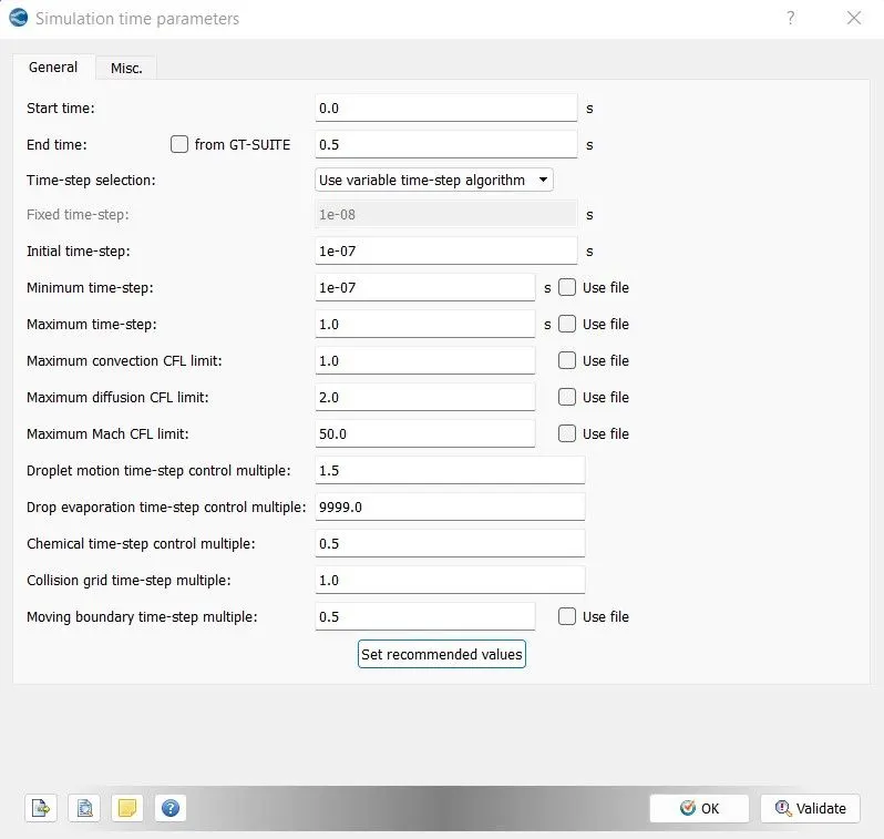
Simulation Time Parameters as follows
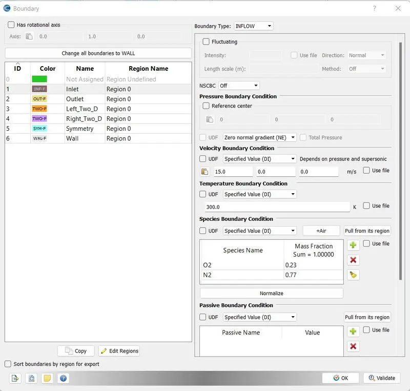
Boundary Condition for Inlet
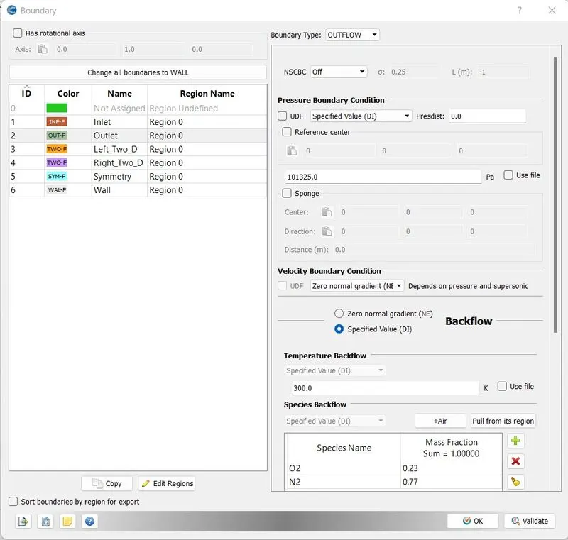
Boundary Condition for Outlet
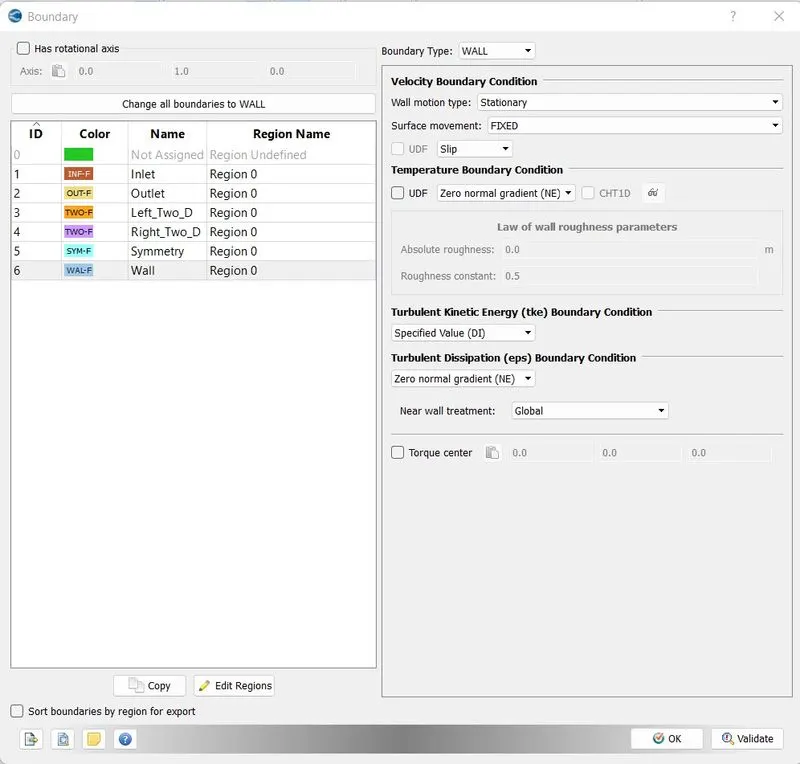
Boundary Condition for Wall, Airfoil
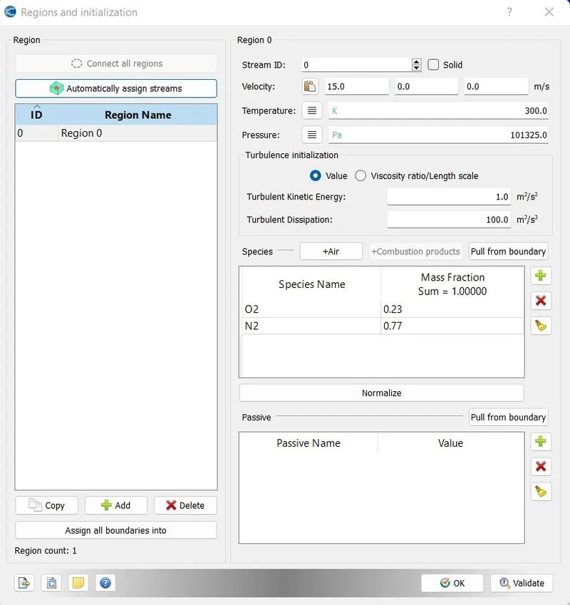
Regions and Initialization as follows
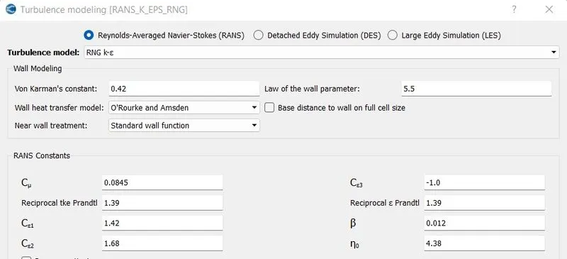
Turbulence Modeling
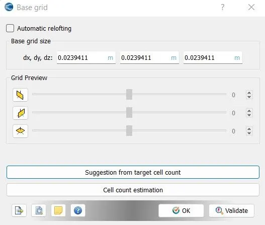
Mesh Size
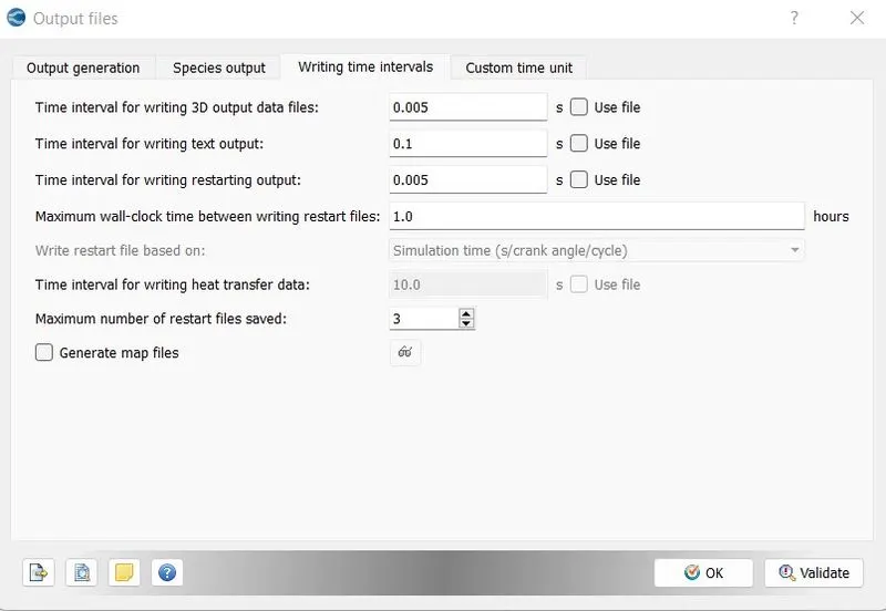
Output Files
Here all the case trees have been set up, now we need to export all the input files and run the simulation using Cygwin software.
After running the software, we need to convert the ran binary file to Paraview readable format using converge.
In this question we have 4 different cases to check with, each cases is different in the change of the Angle of attack of the airfoil.
- Angle of attack = 1º
- Angle of attack = 5º
- Angle of attack = 10º
- Angle of attack = 15º
RESULTS
CASE 1 -
- Angle of attack = 1º
The pressure contour on the 100th cycle when AOA is 1 degree.
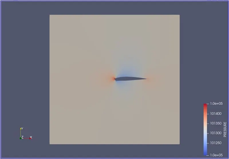
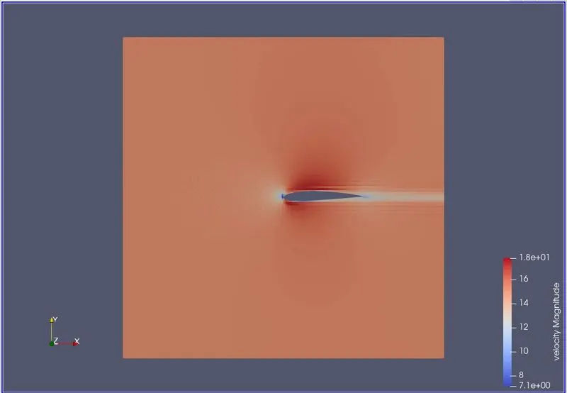
The Velocity contour on the 100th cycle when AOA is 1 degree.
Case 2
- Angle of attack = 5º
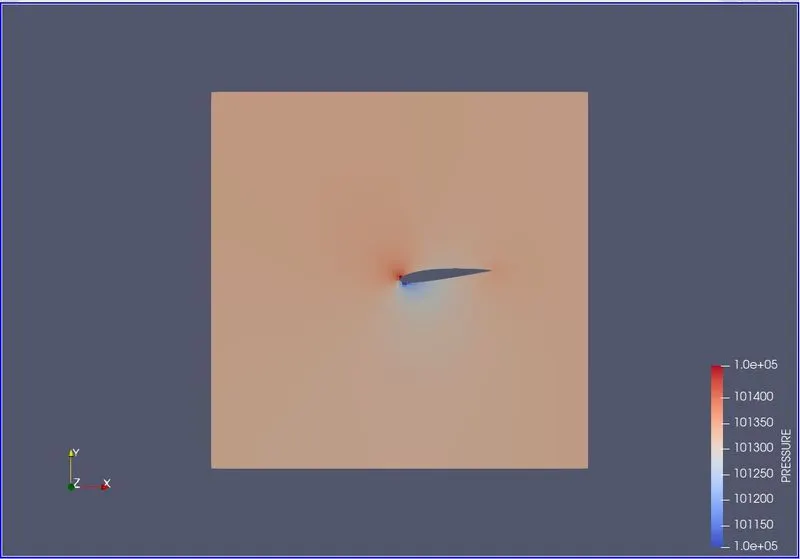
The pressure contour on the 100th cycle when AOA is 5 degree.
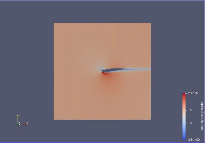
The Velocity contour on the 100th cycle when AOA is 5 degree.
Case 3
- Angle of attack = 10º
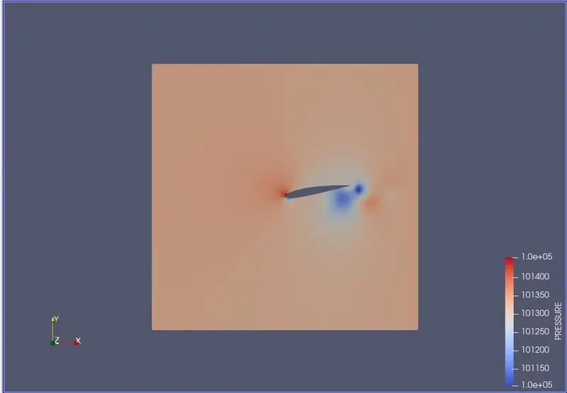
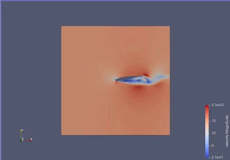
The pressure contour on the 100th cycle when AOA is 10 degree.
The Velocity contour on the 100th cycle when AOA is 5 degree.
Case 4
- Angle of attack = 15º
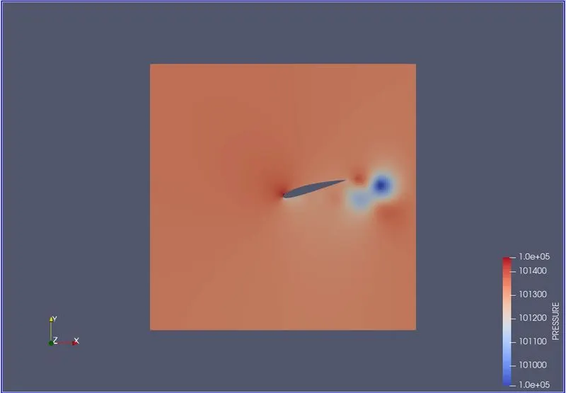
The pressure contour on the 100th cycle when AOA is 15 degree.
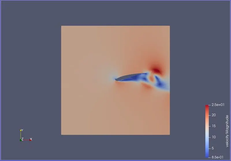
The Velocity contour on the 100th cycle when AOA is 15 degree.
Conclusion
As you can see as the AOA of the airfoil increases, more wake region or negative pressure region is created behind the airfoil. This increases the drag force and Lift.
Youtube video links
Airfoil simulation of Velocity when AOA is 1 Degree
Airfoil simulation of Pressure when AOA is 1 Degree
Airfoil simulation of Pressure when AOA is 5 Degree
Airfoil simulation of Pressure when AOA is 10 Degree
Airfoil simulation of Pressure when AOA is 15 Degree
Airfoil simulation of Velocity when AOA is 15 Degree
Thank You!!