Week 11: Project 2 - Emission characterization on a CAT3410 engine
AIM: To simulate, analyze, and compare the significances of both omega and open w pistons.
INTRODUCTION: In this project, I will demonstrate the diesel engine simulation and the characteristic difference between open w type piston and omega type piston.
- The simulation will be a close sector analysis with a 60-degree angle and this includes on fuel injector nozzle.
THEORY: I will illustrate the step-by-step procedure to construct a complete setup to begin and analyze the simulation.
GEOMETRY:
- In this analysis, I have performed simulation on close sector surface/geometry.
- To make the sector surface we need the geometry file. By using the "Make engine sector surface" tool we can create a surface file.
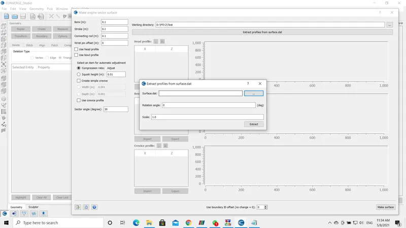
- To extract the sector files, upload the surface file in the below-shown dialog box and click on extract.
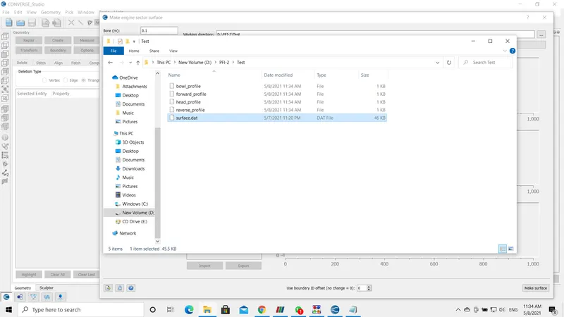
- A set of files are generated in the directory as shown in the second picture.
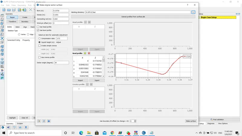
- Next, open the same toolbox to extract the geometry. Enter the dimensions of the Bore, Stroke, and Connecting Rod. These values are provided in the forum.
- Check the use bowl profile, the compression ratio value is known it is 17.5. The sector angle is set to 60 degrees with one nozzle in it.
- After checking the "use bowl profile" option the bowl profile dialog box activates, import the bowl profile file using the import option situated within the bowl profile box, and click on extract to create sector surface.
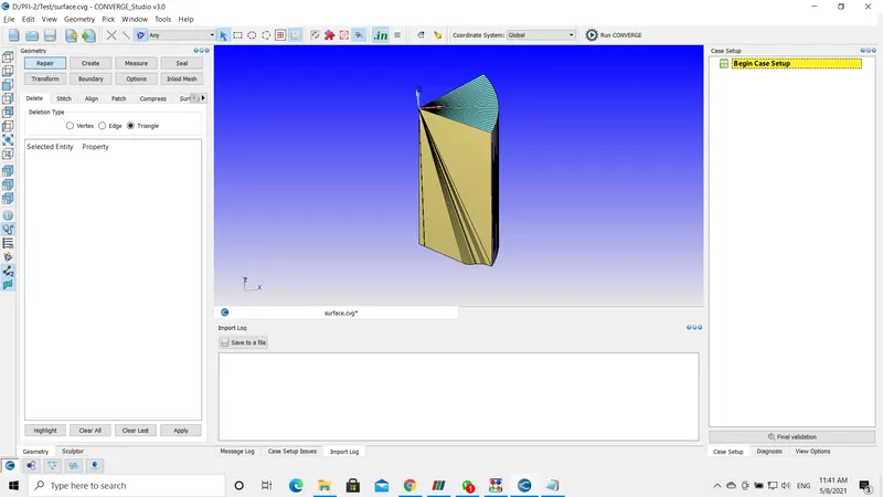
- By using the above mentioned process, I have developed both open-w and omega pistons.
CASE SETUP:
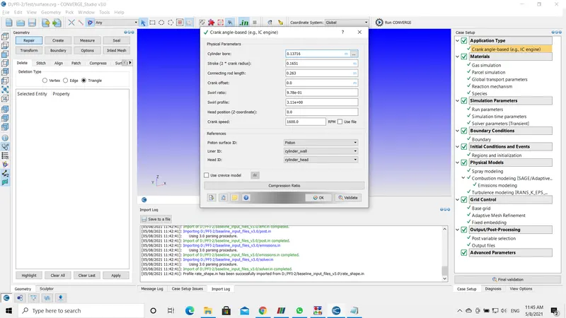
- The above picture shows the crank angle-based IC_Engine setup. The values for this setup are provided in the challenge section.
- In the reference field initially, the ID's are not available we should flag the boundaries and name them in order to get the paths in the reference section.
- I have flagged the boundaries prior to setting up or feeding the values into the application dialogue box.
MATERIALS:
There are a couple of options to be enabled in this section.
- Parcel Simulation.
- Reaction Mechanism.
- Species.
After enabling the above parameters, start setting up the section.
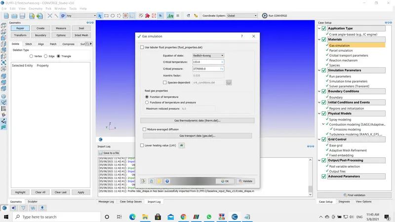
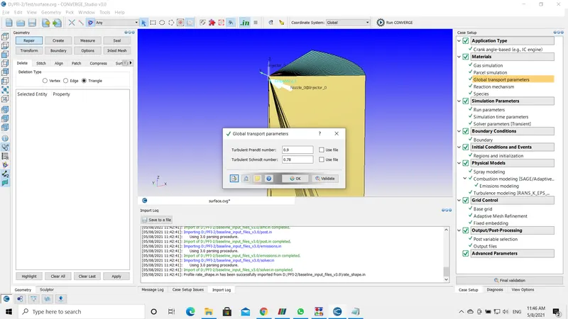
GAS SIMULATION and GLOBAL TRANSPORT PARAMETERS: Use the default options for this parameter. However, we will be using atmospheric air with fuel.
REACTION MECHANISM: It is always advisable to set up a reaction mechanism before setting up the parcel simulation. As we may not find the option we should enable.
- In the reaction mechanism, upload the mech.dat file and check properties. Initial this will show some error because the mechanical files that contain the species in the mech.dat are incomplete without thermodynamic properties.
- So, there will be another file called therm.dat. We can upload the input file by File-> Import -> Import Input File(s) and here upload the desired file.
- Now check the properties, This time the reaction mechanism shows zero errors.

SPECIES:
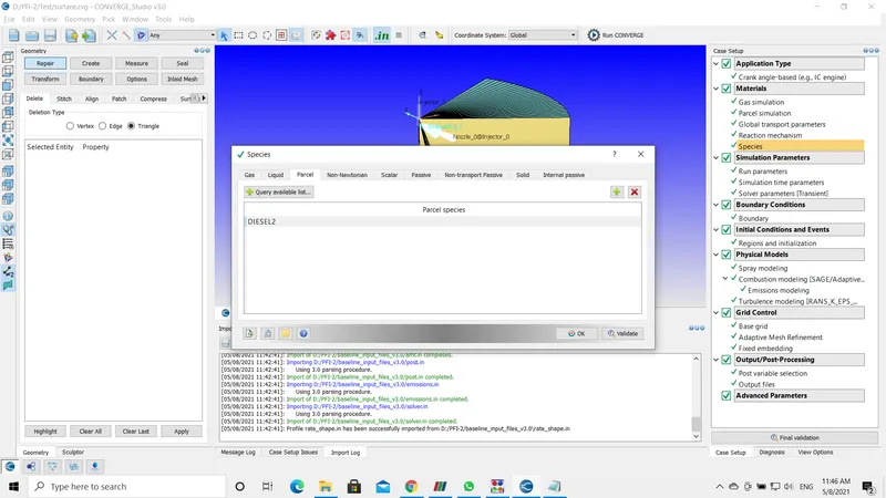
- In species, enable the parcel option and add the DIESEL2 species as shown in the below picture.
- To introduce a new species click on the "PLUS" button on the right side and enter the title.
- With this, the Material setup is completed.
SIMULATION PARAMETERS :
RUN PARAMETERS :
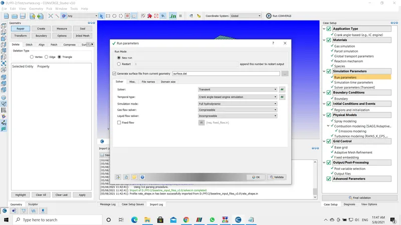
- In run parameters, I am using a transient-based solver with Full-Hydrodynamic mode.
SIMULATION TIME PARAMETERS :
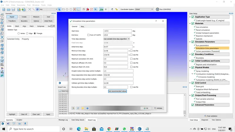
- The starting and ending time is -147 degrees and 135 degrees respectively.
- For other values, I have followed the information provided on the challenge page.
SOLVER PARAMETERS :
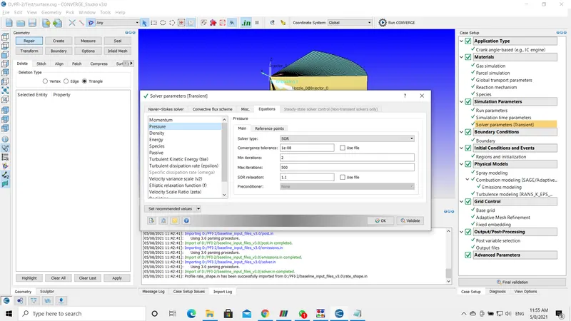
- In solver, parameters use the density-based Navier-Stokes solver.
Boundary Flagging:
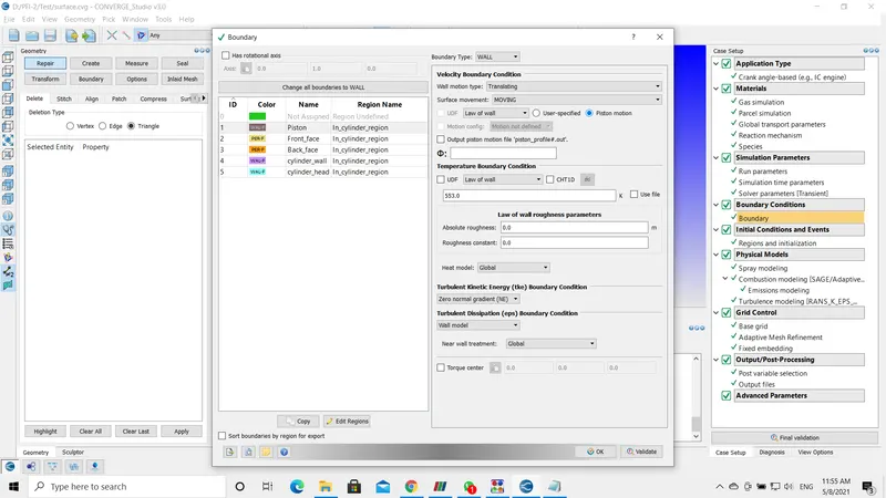
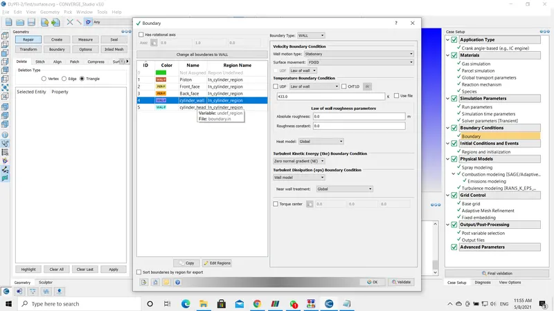
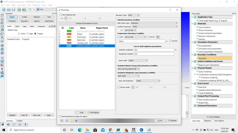
- There are few boundaries in this geometry compared to the complete IC_Engine simulation.
- In piston boundary conditions check the piston motion option.
Initialize Conditions and Events:
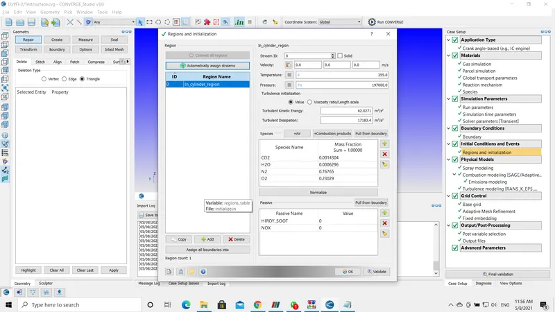
- In this simulation, as this is a close sector analysis we have only one region.
SPRAY MODELING :
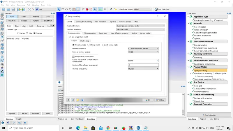
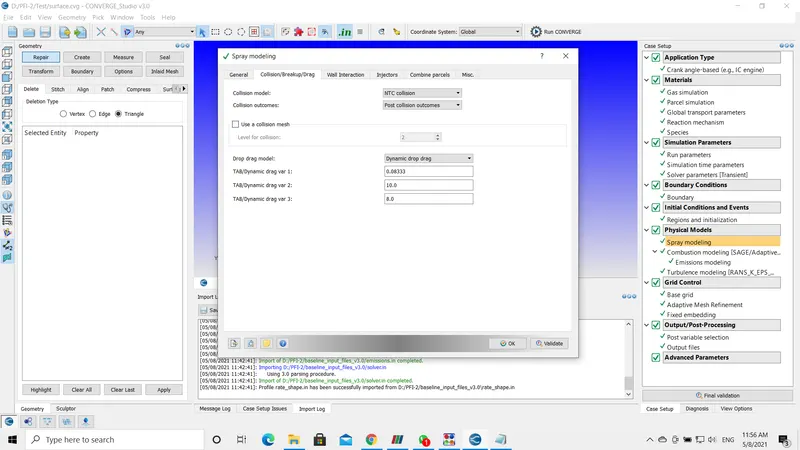
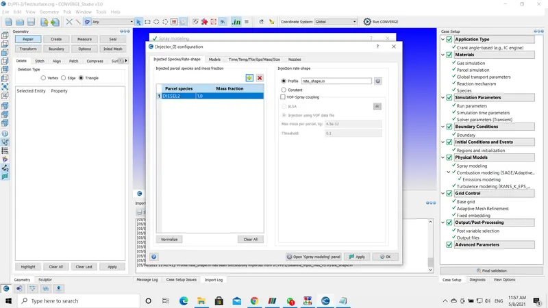
- The spray modeling has several fields to be filled.
- In General setup, the parcel distribution is set to Distribute parcels evenly throughout the cone.
- Turbulent dispersion is set to the O'Rourke model.
- Collison model to NTC collision.
- Collision outcomes to Post-collision outcomes.
- In this simulation, I have used only one nozzle.
- The injector model used is the Kelvin-Helmholtz model. To set up the values for the field we can use recommended values option on the bottom left side of the dialogue box.
- It is important to determine the start of injection, duration of injection, and total mass of injection. These values are also provided on the challenge page.
- Finally, as mentioned in the above line regarding the four nozzle injections, introduce nozzles by selecting the add nozzle button and use the values for each nozzle flow direction or nozzle angle that are provided on the page.
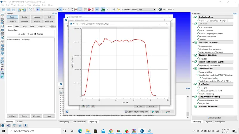
- I have used an input file to generate the rate shape. This input file is experimental data provided in the forum.
COMBUSTION MODELING:
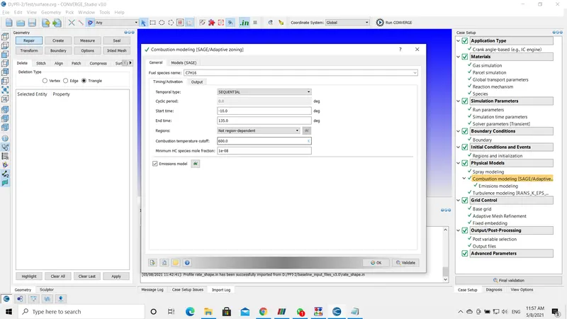
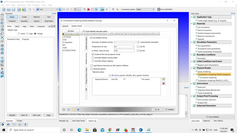
- In this combustion modeling, I have used the SAGE model by using the values provided on the challenge page.
EMISSION MODELING:
TURBULENCE MODELING:
GRID CONTROL:
BASE GRID:
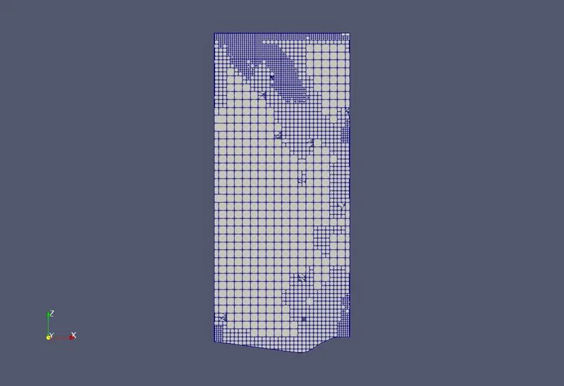
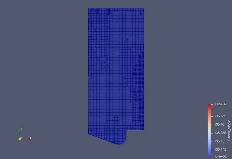
- The rough cell count is estimated for the open-W piston to be 6073 cells.
- The rough cell count is estimated for Omega piston to be 6736.38 cells.
ADAPTIVE MESH REFINEMENT :
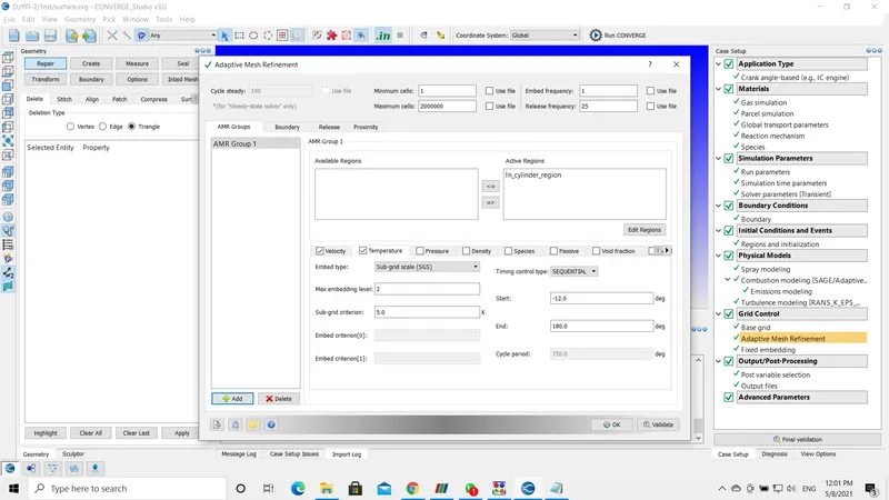
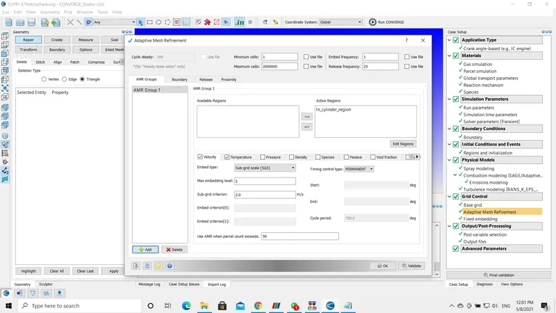
- I have used AMR for temperature and velocity in intake ports 1 & 2, and cylinder head.
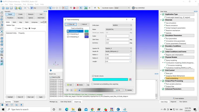
FIXED EMBEDDING :
- I have implemented the fixed embeddings in the nozzle region.
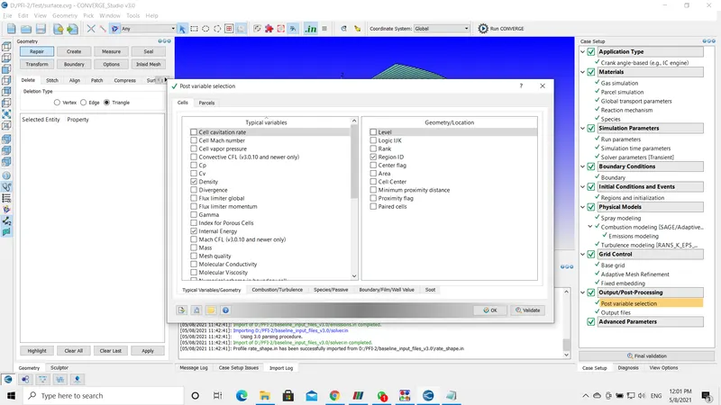
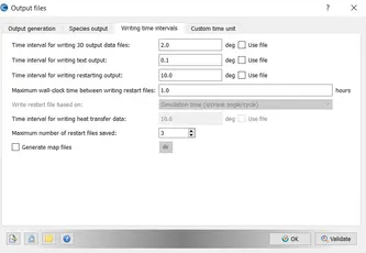
OUTPUT/POST-PROCESSING:
- The values provided in the post variables and output files by default are correct and we can proceed using these values.
EXPLAINATION:
NOZZLES & SPRAY MODELING:
- Parcel distribution is set to "cluster parcels near center", this model injects the fuel to the center of the cone.
- This type of model is suitable for compression ignition engines.
- Fuel after entering into the combustion chamber is affected due to the turbulence characteristics. O'Rourke model gives better performance in solving the turbulence modeling.
- Collision: To calculate the collisions in the Lagrangian spray simulation NTC model is used. In general, when the fuel enters the droplets per parcel is not the same all the time the number varies. So, the NTC (no time counter) is several orders of magnitude faster and slightly more accurate than methods.
- Wall Interaction: I have enabled the spray wall interaction model to wall film, this helps in reflecting or splashing the droplet when it hits the wall. The film model is set to the O'Rourke method.
- Injector: In the injector, I have included the fuel that I am using for the simulation i.e, Diesel2.
- I have also provided a profile for rate shape to a trapezoid. Converge utilizes this profile to inject the total mass according to the given time that I have provided.
- Kelvin-Helmholtz and Rayleigh-Tailor models are the industrial standard models for fuel injection with standard values. These values describe the parcel breakup and time taken for a parcel to get unstable.
- Nozzles: In this simulation, I am using a compression ignition engine the injector is situated at the center of the cylinder.
- On the other hand, we can also locate the center by using the measure option.
- The final part of the nozzles is the injection pressure. The injection pressure is automatically solved by the converge by using the initial conditions such as rpm, injection duration, total mass injected, discharge coefficient.
COMBUSTION MODELING:
- SAGE type of combustion model is used and multi-zone model to speed up the combustion calculations.
- Firstly, the type of fuel used for combustion is mentioned, Next the start time, end time, and the cyclic period.
- For the start time, the combustion model is set to start a few degrees before the spark takes place so as to initiate the combustion calculation.
- The end time is the same as the exhaust valve closing time.
ADAPTIVE MESH REFINEMENT (AMR):
- In numerical analysis, AMR is a method of adapting the accuracy of a solution within certain sensitive turbulent regions of simulation, dynamically and during the time the solution is being calculated.
- When solutions are calculated numerically, they are often limited to pre-determined quantified grids as in the cartesian plane which constitutes the computational grid, or mesh.
- Many problems in numerical analysis, however, do not need a uniform precision in the numerical grids used for plotting or computational simulation and would be better suited if specific areas of graphs need precision. AMR provides such a dynamic programming environment for adapting the precision of the numerical computational based on the requirements of a computation problem in specified locations.
- Subgrid criteria (SGS) is an integral part of AMR. As the AMR is used for different parameters Temperature, Velocity, Pressure, and Species, etc.
- The SGS is provided with a predefined value. If the parameter exceeds the specified value in the SGS, the AMR automatically enables.
FIXED EMBEDDING:
- Fixed Embedding is a smart feature. It helps in adding extra mesh in specified locations.
- This offers numerous benefits including the ability to apply more cells near a wall and get an increase in accuracy and running a fast coarse mesh without distorting the geometric representation.
- The following regions and boundaries included in fixed embedding including, Intake valves, Exhaust valves, Cylinder region, nozzles, and sparkplugs.
- The fixed embedding act as an additional refinement in that areas.
- For example in the cylinder region, the energy emitted through the source term resides for a longer period of time and numerical diffusion takes place.
- The fixed embedding is active for a very small duration of time, helps in capturing the better seed values, temperature gradients.
- This also initiates AMR to be activated in that region or a particular area.
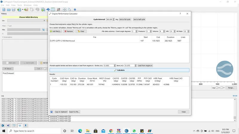
OPEN-W PISTON ENGINE PERFORMANCE:
Power(P) = (2⋅π⋅N⋅T2⋅�⋅�⋅�)/60
Power = Work/Time.
Work = 481.931 N-m
Time = Duration(deg)/Degrees Per Second =240.199/18000=0.0133 Seconds.
Power = 481.931/0.0133 = 36235.413 KJ or 36.235 KW
N (RPM) = 3000
P=(2⋅π⋅N⋅T2⋅�⋅�⋅�)
36.235*60/2*pi*3000 =T
T= 34819.14*60/2*pi*3000
T= 11534.09 N-m
OMEGA PISTON ENGINE PERFORMANCE:
Power(P) = (2⋅π⋅N⋅T2⋅�⋅�⋅�)/60
Power = Work/Time.
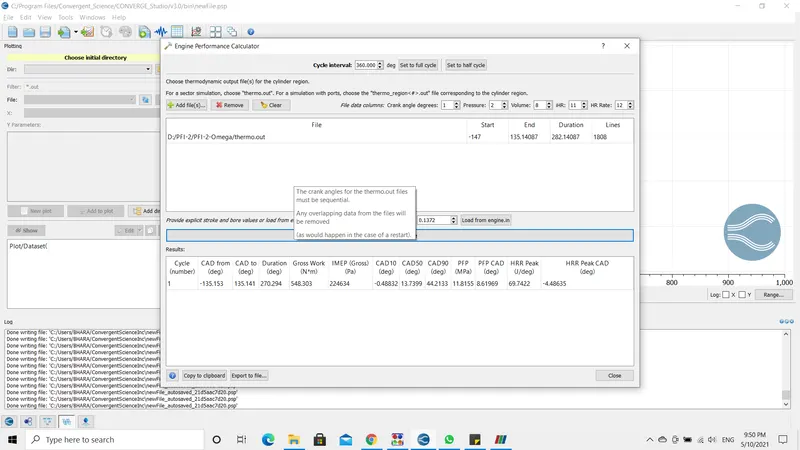
Work =548.303 N-m
Time = Duration(deg)/Degrees Per Second =240.199/18000=0.0133 Seconds.
Power = 548.303/0.0133 = 41225.789 KJ or 41.225 KW
N (RPM) = 3000
P=(2⋅π⋅N⋅T2⋅�⋅�⋅�)
T= 41225.789*60/2*pi*3000
T= 13122.576 N-m
RESULTS :
- PRESSURE PLOT
- TEMPERATURE PLOT
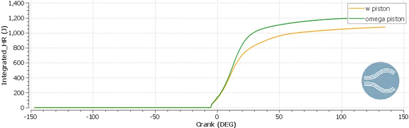
- INTEGRATED_HEAT RELEASE PLOT
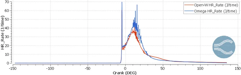
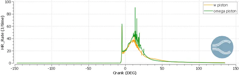
- HEAT RELEASE PLOT
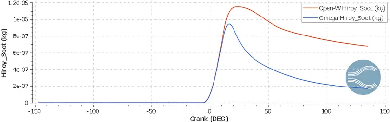
- SOOT PLOT
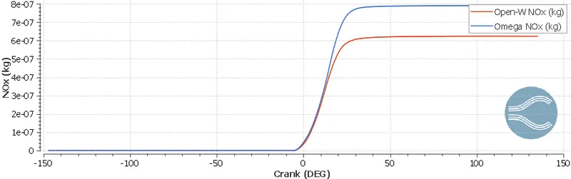
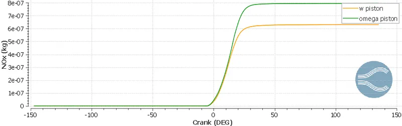
- NOx PLOT
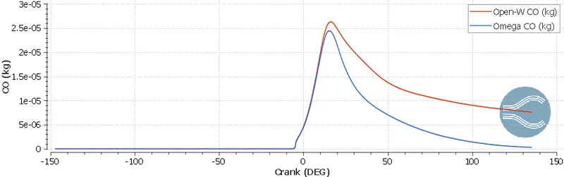
- CO-EMISSION PLOT
- CO2-EMISSION PLOT
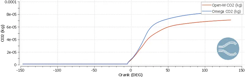
- HC-EMISSION PLOT
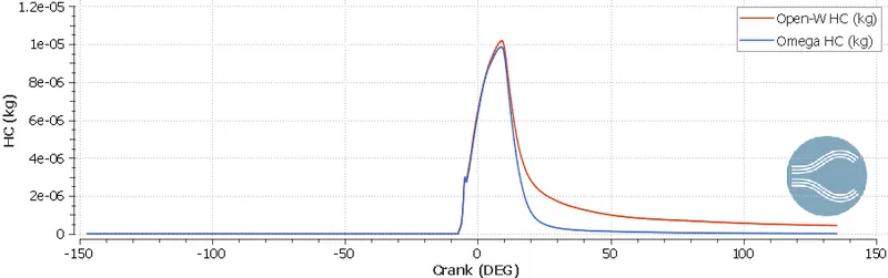
Useful plots and animations were generated to compare the piston profiles. Its very difficult to choose one of the them, because they have their own advantages. Animations were created to see spray wall interaction and piston movement.
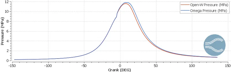
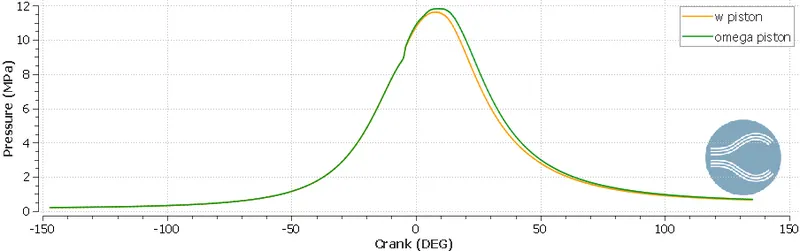
1. We if look at the pressure plot, we can see we are getting higher pressure by omega piston, but we cannot declare it best only on this criteria.
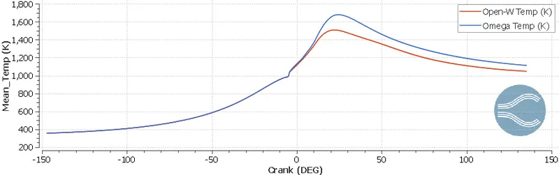
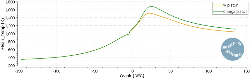
2. Now, look at the mean temperature plot. For w piston mean temperature is low, we can assume there might be some fuel which is unburn, but we have to see further criteria to validate it. Low temperature gives us lower amount of NOx as well.
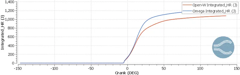
3. Now come to heat rate and integrated heat rate plots. Omega piston has higher heat release rate, that why it has higher temperature compared to omega piston. Integrated heat release rate is accumulation of heat released during whole cycle. IHR is higher for omega piston.
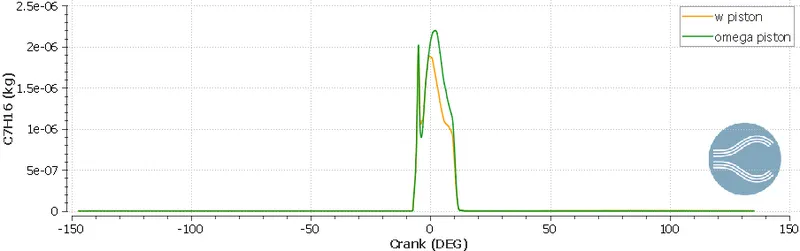
4. If we look the following plot, we can say omega piston has higher gases fuel, which is being burned lately, it can be verified from IHR plot also.
5. With omega piston there is lower NOx and it can be selected, if it someone targets lower NOx.
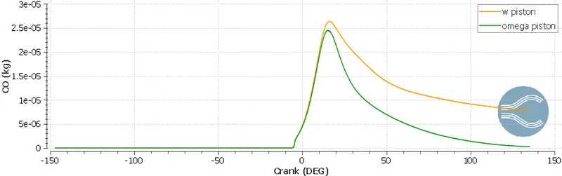
6. Open w piston has larger amount of carbon mono oxide, so we can say there is a lot of unburn fuel.
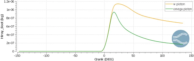
7. Omega piston produces lower soot, again, someone can choose it, if he is targeting lower Soot.
CONCLUSION:
- To begin with, This is a transient simulation with the FULL-HYDRO model. The simulation start cycle and end cycles are -147 degrees and 135 degrees.
- In this simulation, I have performed a close sector surface analysis. In this type of analysis, the inlet ports, exhaust ports, inlet valves, exhaust valves are ignored the simulation performs the calculation on the piston or the combustion chamber as shown in the initial steps and pictures.
- "make engine sector surface" tool develops a part of piston with a specified angle.
- In the toolbox, the sector angle is specified to be 60 degrees that mean the injector has six nozzles inside the combustion chamber (360/60 = 6).
- The benefits of close sector surface are it reduces the computational cost, by eradicating the ports and valves the simulation time decreases, and this also helps in concentrating the characteristic changes inside the combustion chamber.
- From the above plots, it is observed that the pressure and temperature inside the "omega" type piston are greater than the "open-w" type piston.
- There is not much difference in pressure value but there a considerable difference between omega and open-w piston temperature gradients.
- The peak pressure attained by the omega piston and the open-w piston is closer to 12 MPa. The peak temperature attained by both pistons are omega=1.7e+03 K and open-w = 1.5e+03 K.
- The heat released or generated by the omega piston is also far greater than the open-w piston. Omega piston has released around 1200 J of heat, while the open-w piston has released nearly 1100 J of heat.
- The soot production i.e., incomplete burned particles that contained a large amount of amorphous carbon is very high in the open-w piston. On the other hand, the NOx i.e., Nitrogen Oxide produced by the open-w piston is far lesser than the omega piston.
- The carbon emissions from the omega pistons are also greater than the open-w piston(CO and HC), despite it emits fewer carbon di-oxides.
- The above animations represent the Pressure and Temperature inside the pistons. After referring to the animations I came to a conclusion that higher pressure and temperature inside the omega piston is due to it design advantage. The omega bowl has more volume than the open-w piston which increases the pressure and temperature.
- If the pressure and temperature are higher inside the temperature the fuel burns completely and helps to reduce the soot produced.
- From the engine performance calculations, the omega piston has more torque than compared to the open-w piston.
- Due to environmental restrictions and concerns, omega piston may not be suitable for current scenarios.
- In my point of view, the Omega piston could be used for logistic and transportation purposes because of its design advantages, high power, and torque.