Week 3: Flow over a backward facing step
Answer
This is a simple geometry for the analysis of a fluid through a backward-facing step.
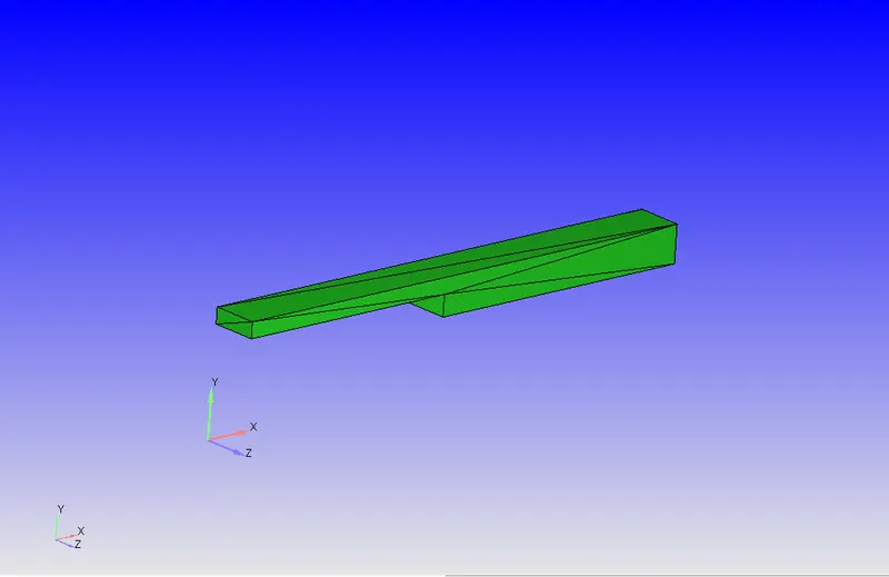
Firstly, we need to scale down the geometry as its a big so simulation time will be huge, so we re-scaled to 0.001.
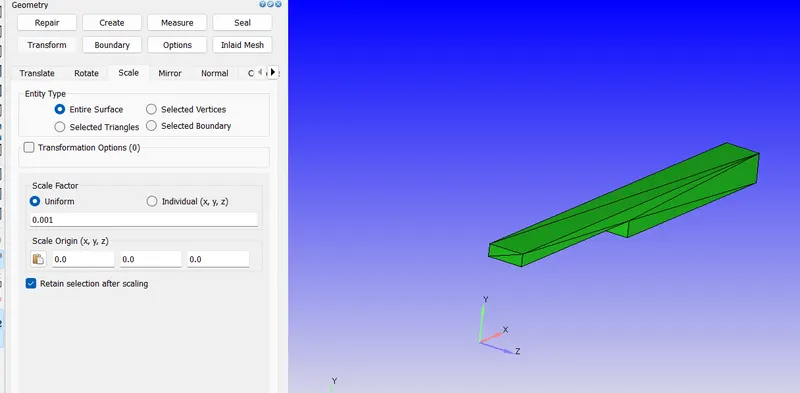
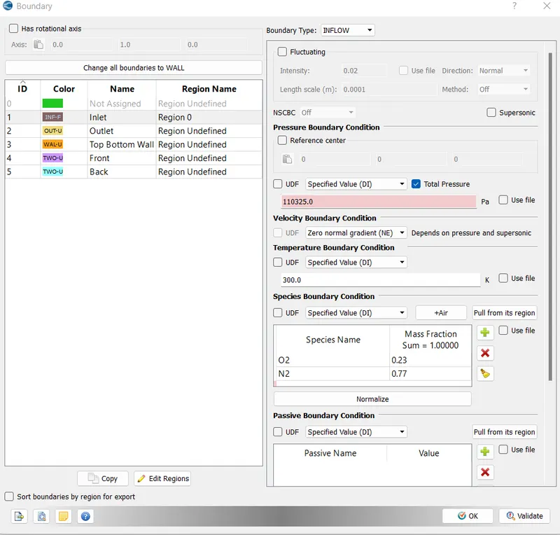
Boundary condition
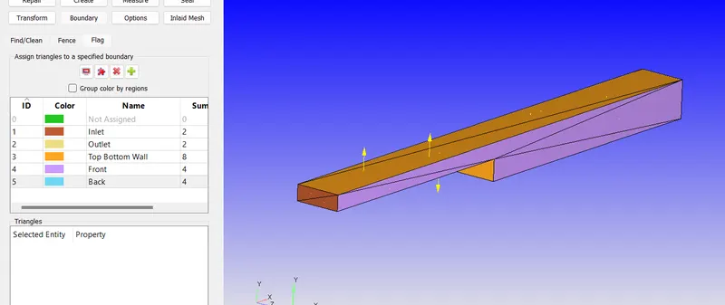
Make the Gas simulation as Default
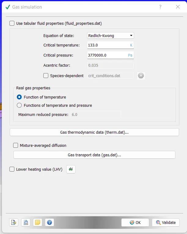
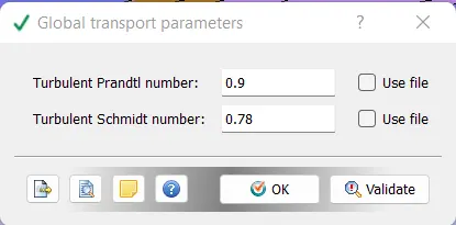
Global Transport Parameters - make it default
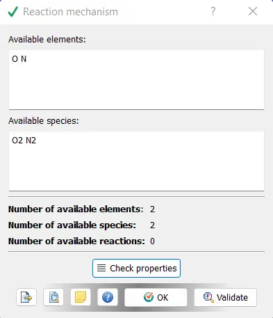
reaction mechanicsm
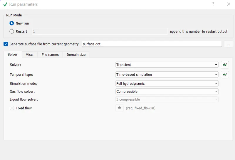
Simulation time parameter
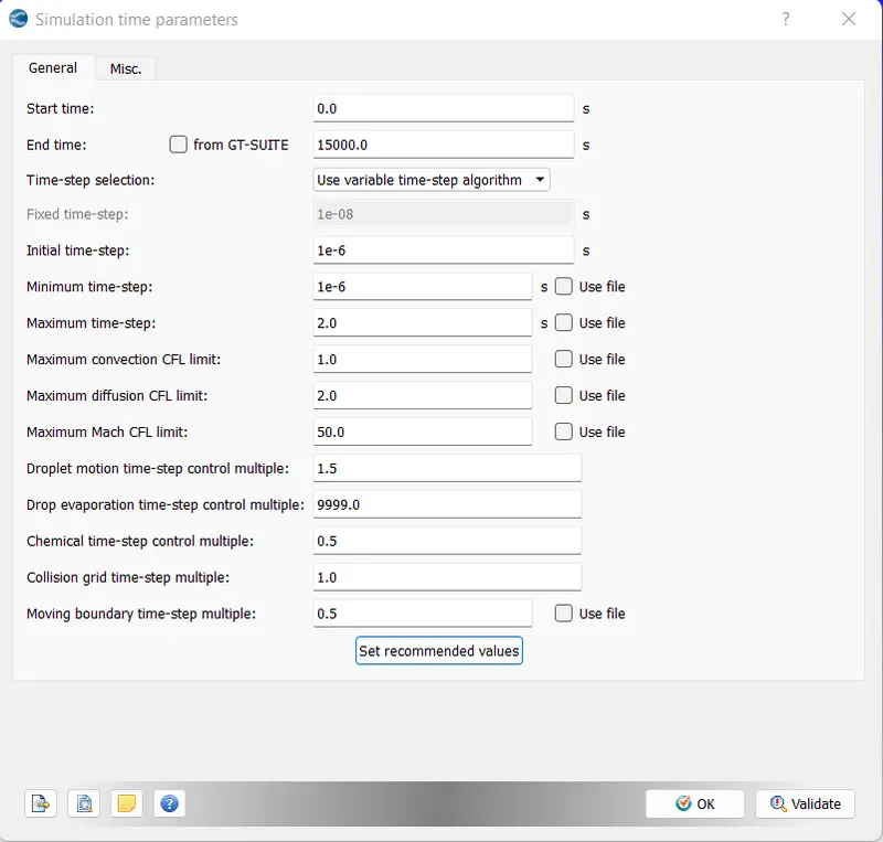
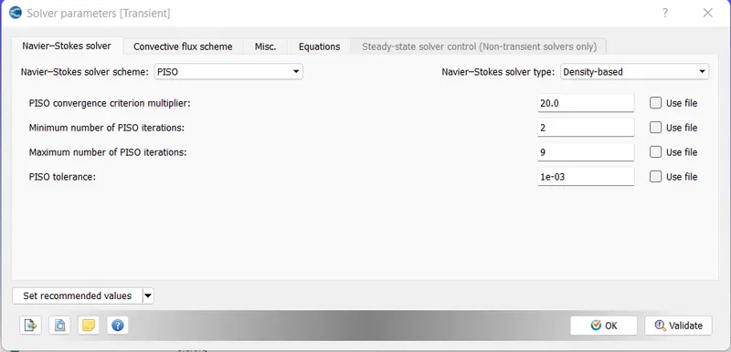
Solver Parameter
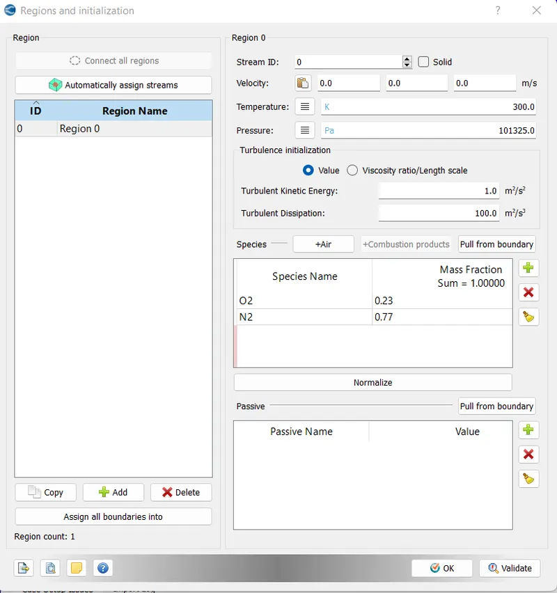
Regions and Initializations
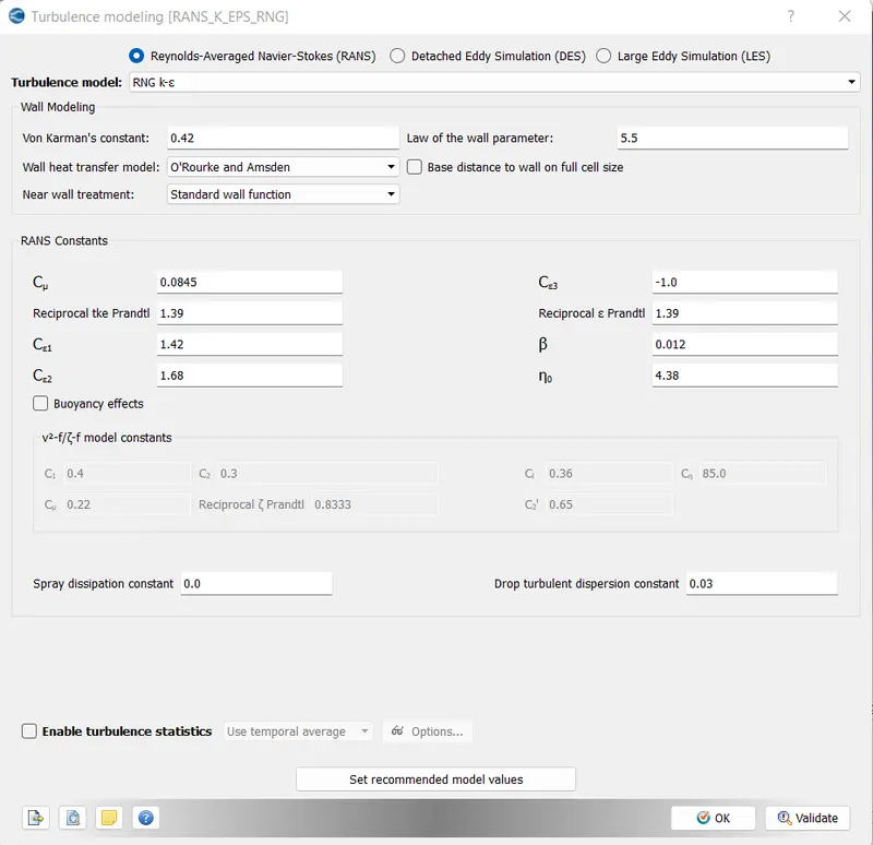
Turbulemce Modelling
Case I
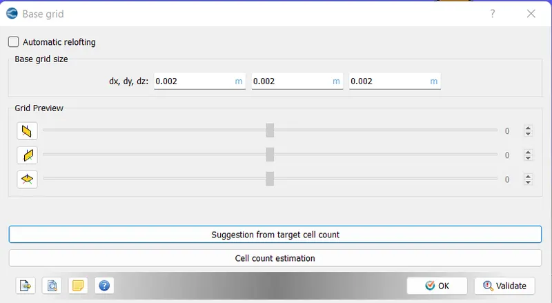
- dx = dy = dz =2e-3m
Base Grid
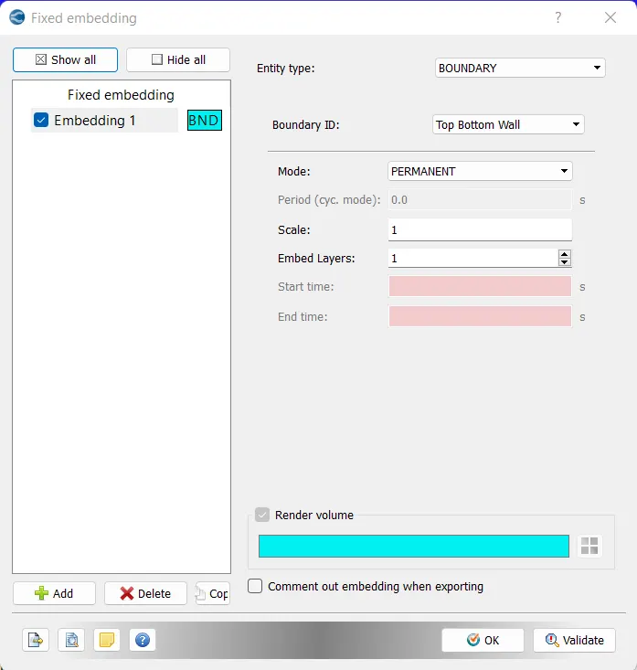
Boundary Conditions
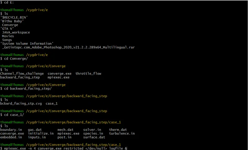
Now we need to run the simulation using Cygwin using the commands
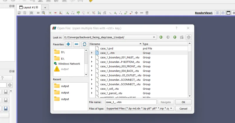
We use converge to convert the files to paraview readeble files
In paraview the .vtm files is opened and click apply
the CAD in paraview
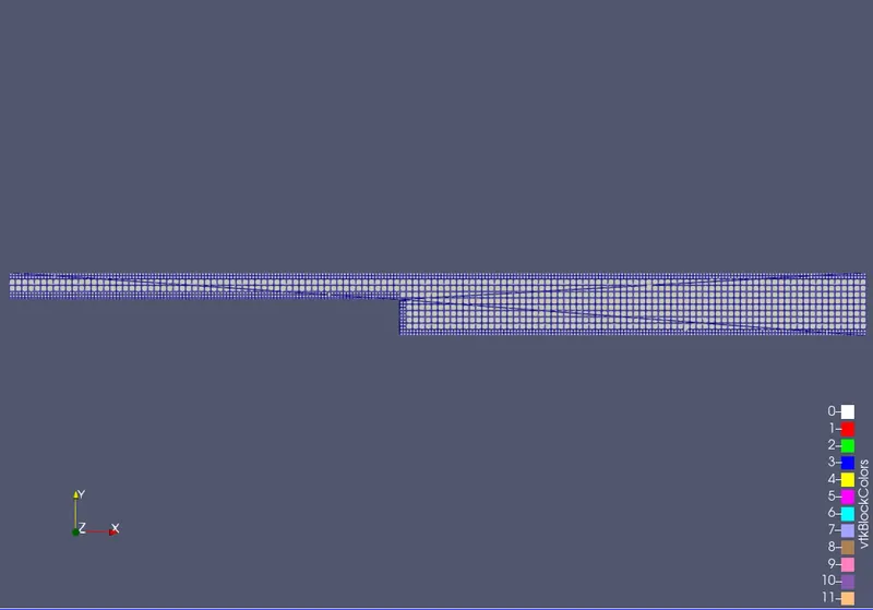
the velocity contour
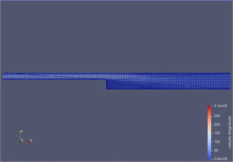
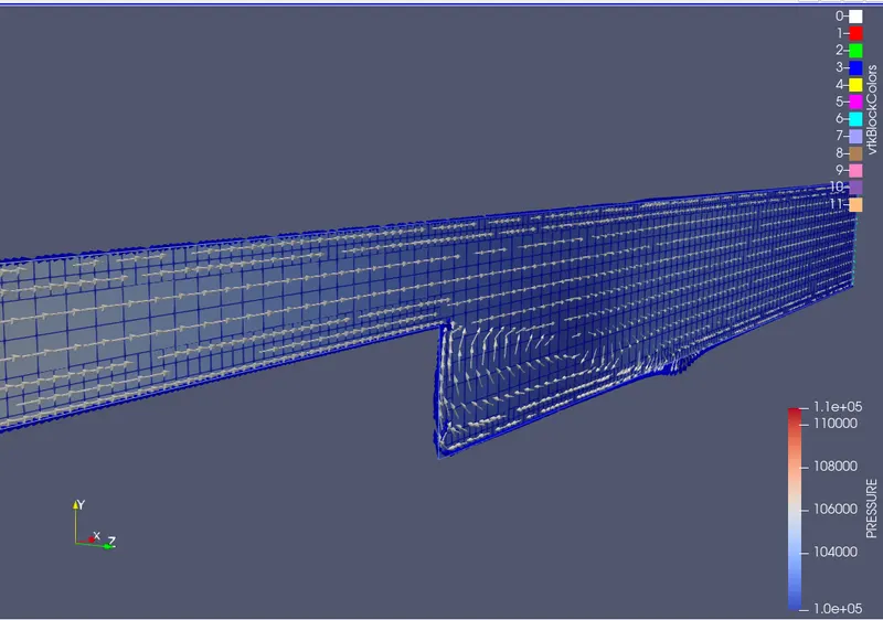
The Pressure contour
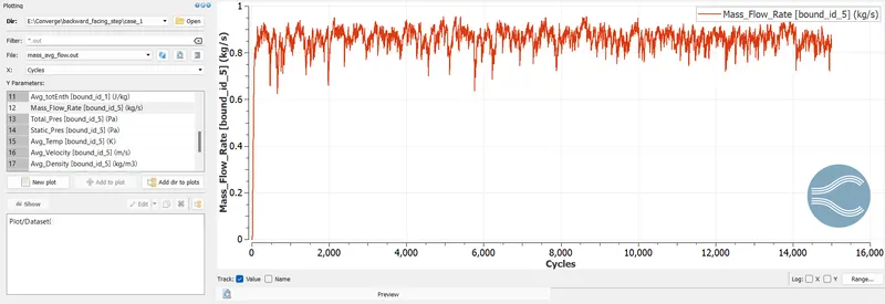
Line plot showing mass flow rate
Total Cell Count
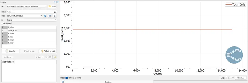
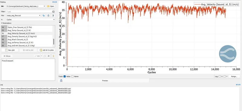
Average velocity at outlet
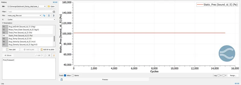
Static Pressure at Boundary
************************************************Case 2 *********************************************************
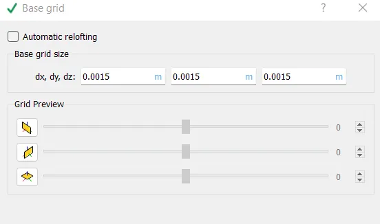
- dx = dy = dz =1.5e-3m
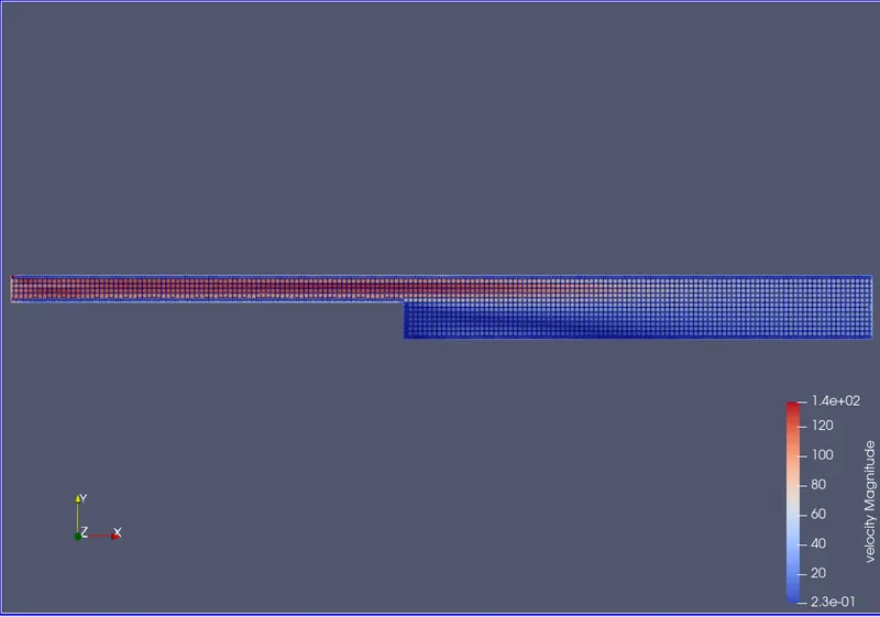
Velocity Magnitude
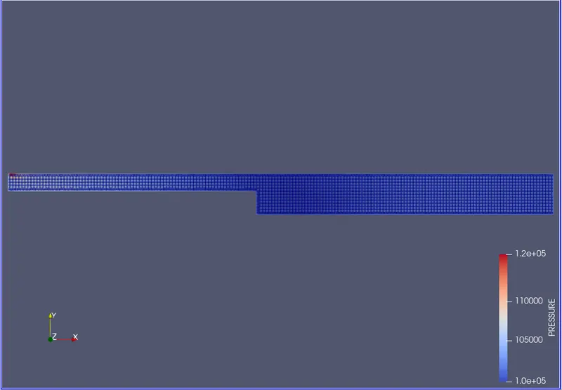
Pressure
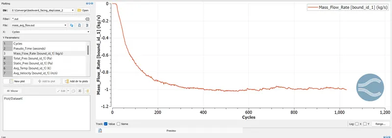
Line graph showing mass flow rate
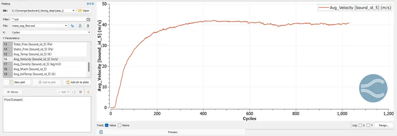
Average velocity at outlet
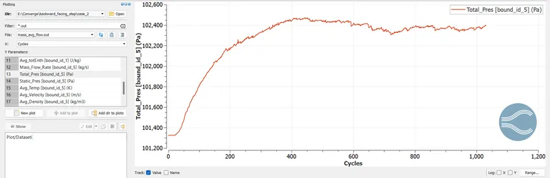
Total pressure at outlet
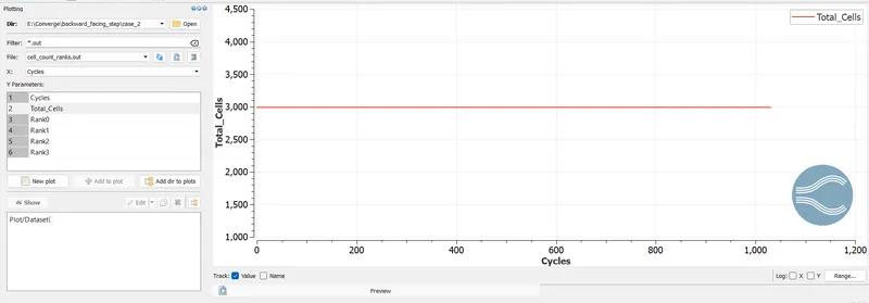
Total Cell count
*********************************************CASE 3 ************************************************************
dx = dy = dz =1.0e-3m
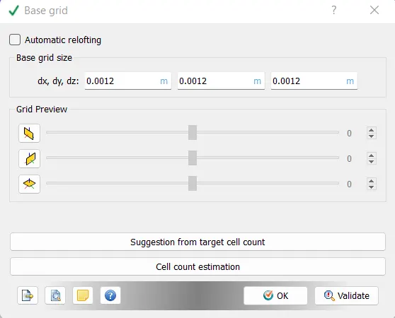
results
velocity
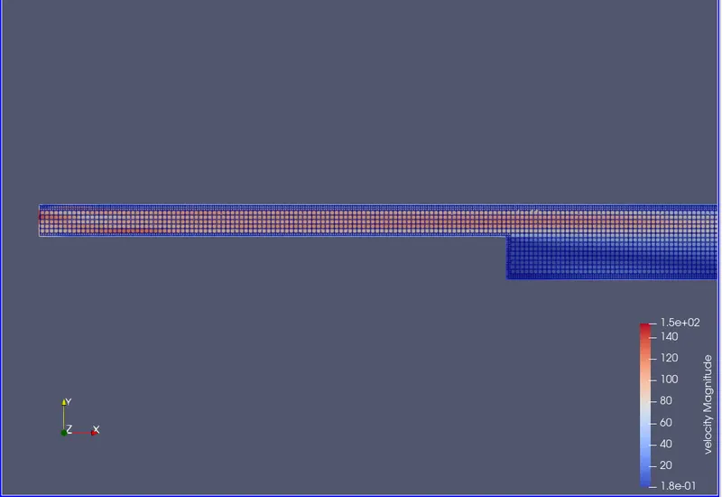
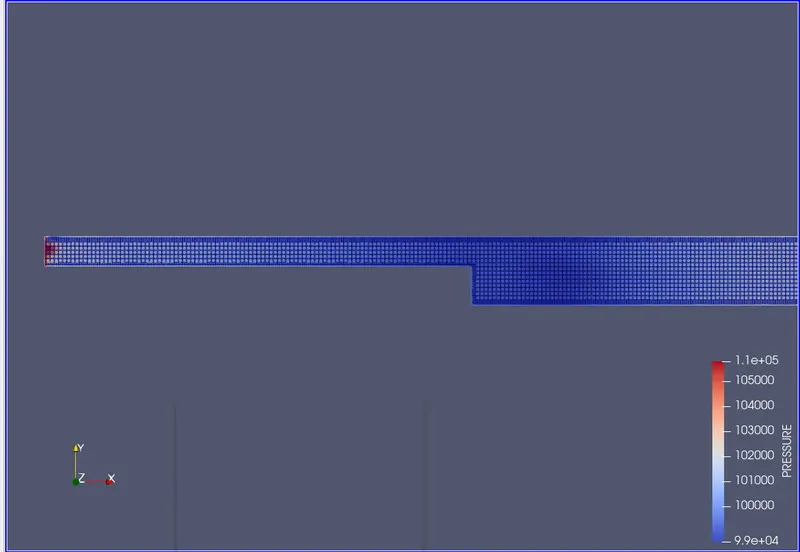
Pressure contour
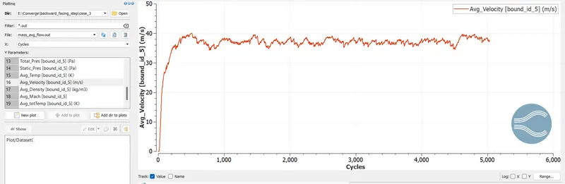
Velocity at outlet
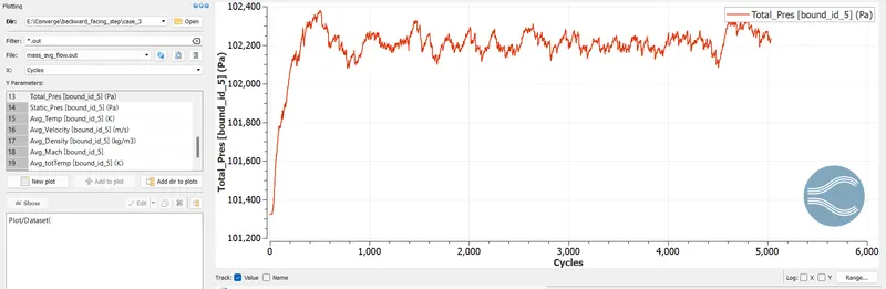
Pressure At outlet
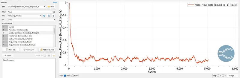
Mass flow rate at boundary
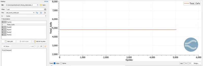
Total cell count
Also explain where and why separation is taking place in detail.
The separation of the air flow takes place at the point where the area of the cross-section increases, that is at the edge inside the box
thank you