Week 9: Project 1 - Surface preparation and Boundary Flagging (PFI)
Objective
To make NO HYDRO case set up of an IC engine. Make boundary flagging and complete the whole set up in order to figure out if the Geometry moves correctly during the run.
Geometry
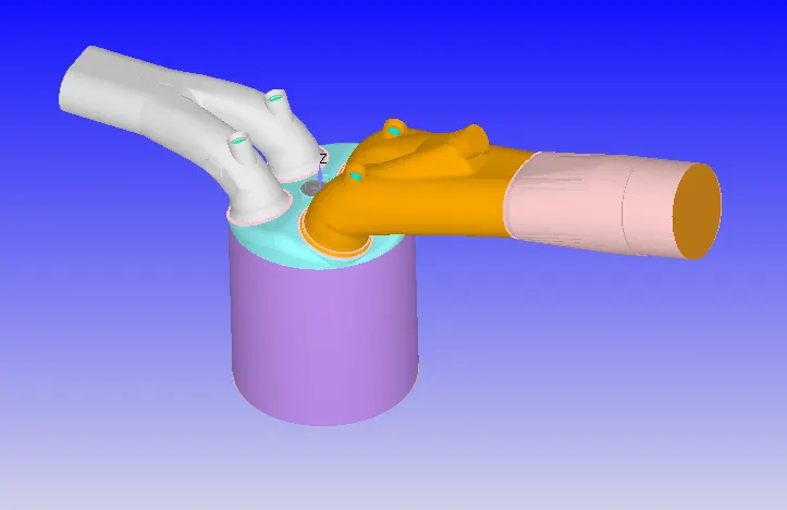
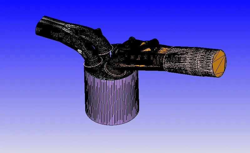
Boundary Flagging
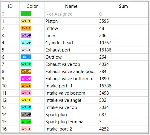
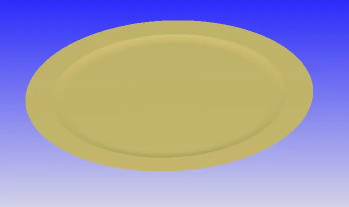
- Piston (Piston Head)
- Inflow (Inlet) Marked as Red
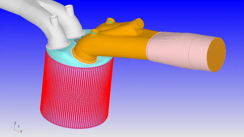
- liner (Marked in Red)
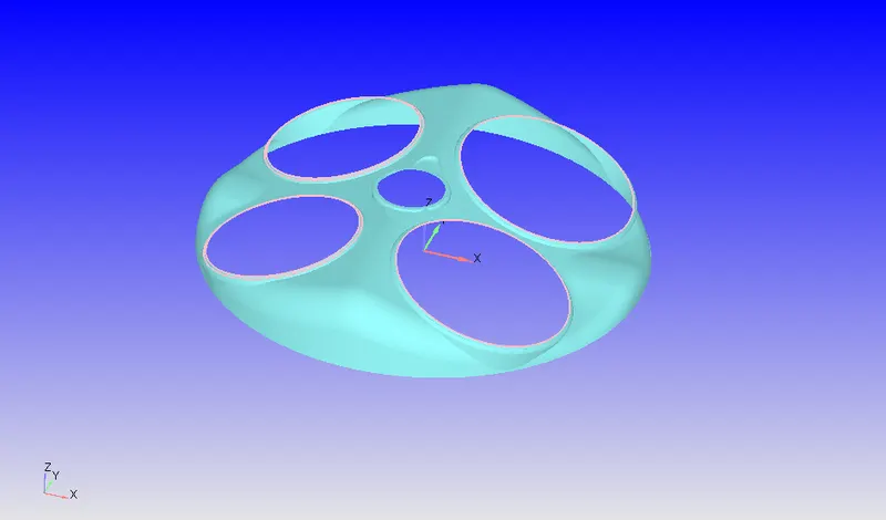
- Cylinder Head
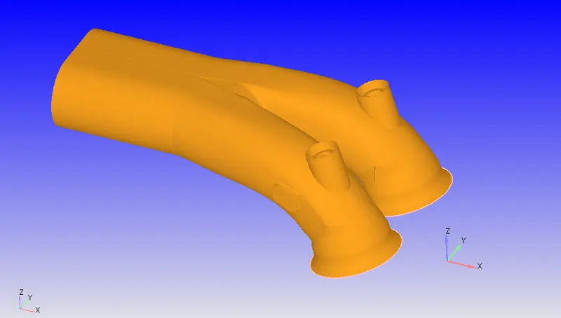
- Exhaust port
- Outflow
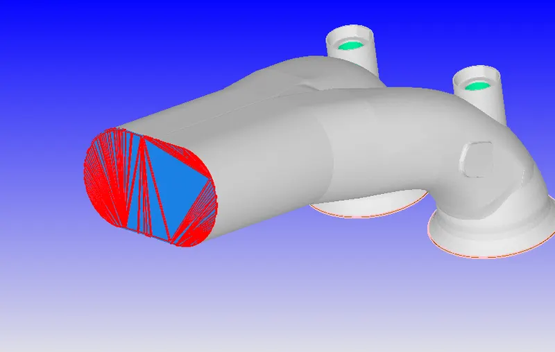
- Exhaust Valve top, angle and bottom
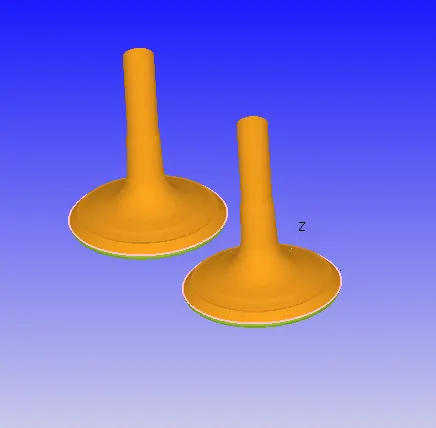
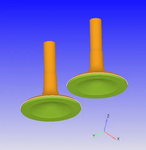
Exhaust valve top and angle belongs to exhaust region, while valve bottom belongs to the cylinder region.
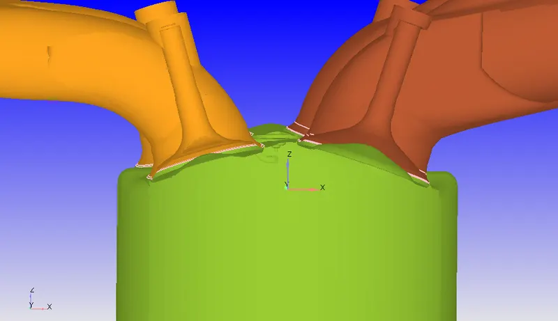
As you see while Grouping color by region we see that Valve geometry are divided into 2 regions.
First orange colored region is Exhaust region and the green one is called Cylinder region (Cylinder where the combustion takes place). this division is made intentionally to restrict the flow in the cylinder region.
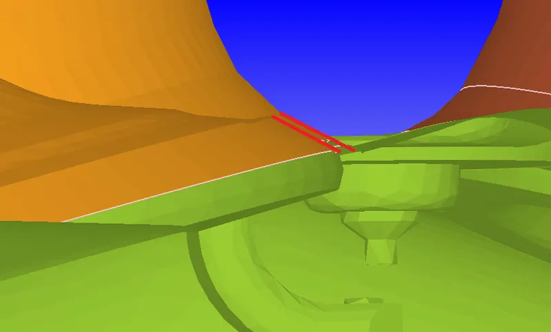
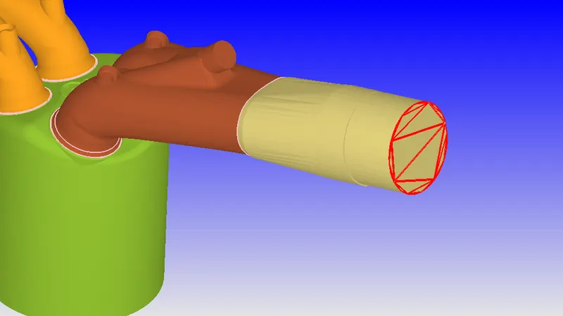
As you see the valve is open (marked with the red lines), therefore we need concept called "Disconnect triangles" in order to avoid airflow between this little gap when the valve is considered to be closed. If the Disconnect triangles were not present then simulation will underpredict mass flow in the combustion region.
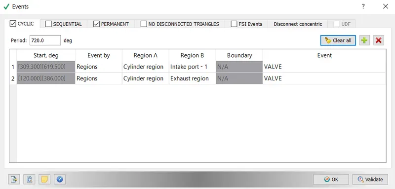
we activate "disconnect triangles" with the "events".
- Intake ports
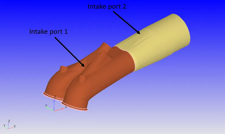
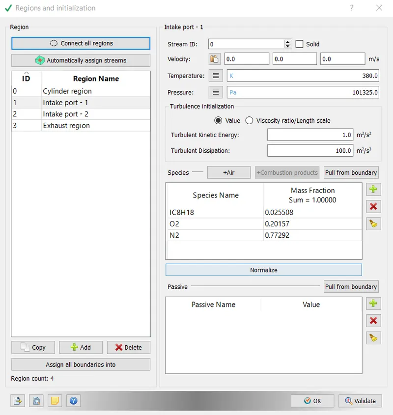
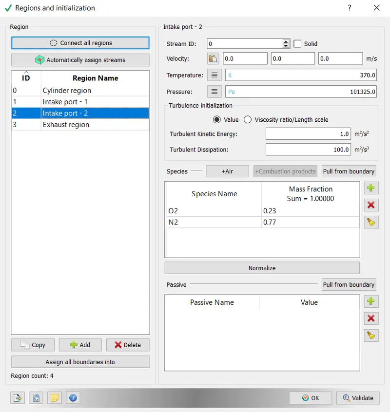
We divide intake ports into 2 regions as shown above. In the intake port 2 only air is present, however in the Intake port 2 fuel spray is also introduced.
- Intake valve top, angle and bottom
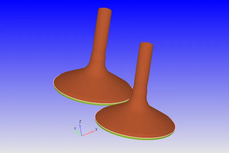
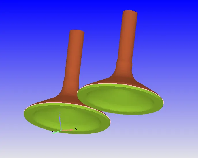
Intake valve top and angle belongs to the Intake port_1, while valve bottom belongs to the Cylinder region. The reason is the same as for the Exhaust valve, discussed above.
- spark plug
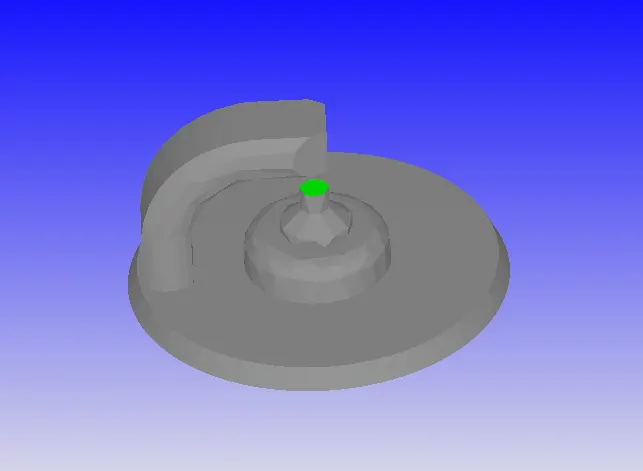
In the grey color we have the spark plug itself, while in the green boundary is named as a "spark plug terminal" place where the spark is created.
NO HYDRO case setup
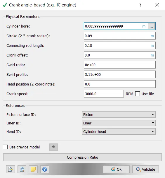
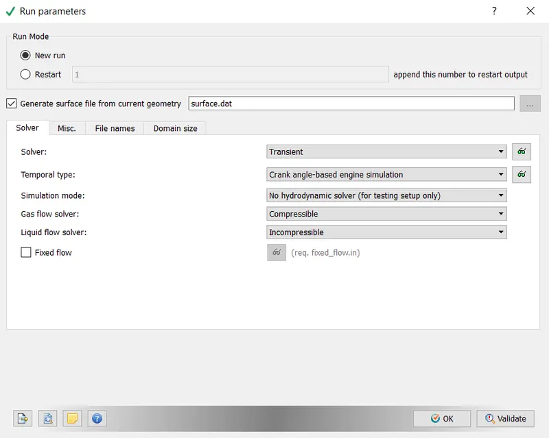
- Crank angle-based
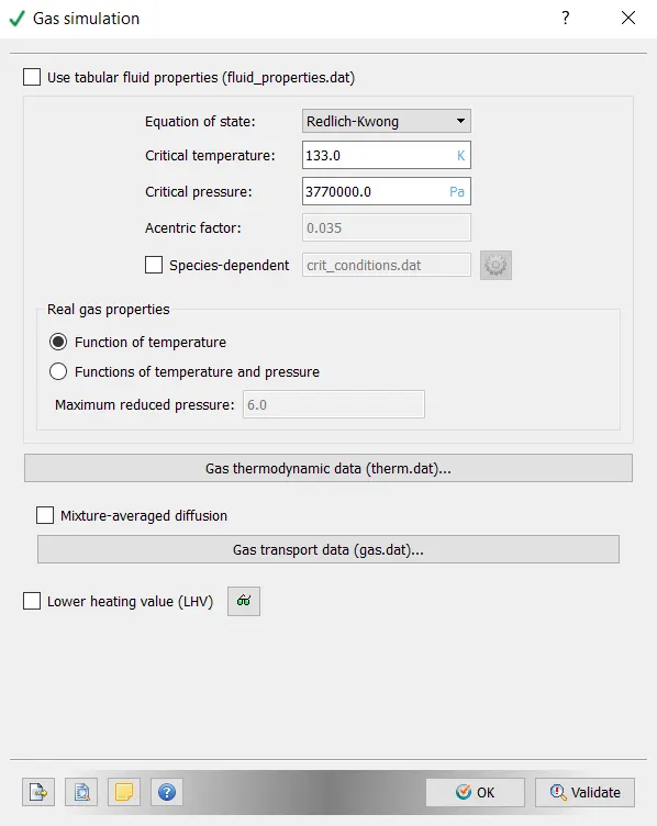
- Real gas (AIR)
- Reaction Mechanism
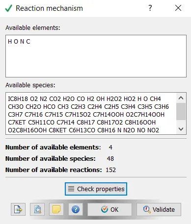
Reaction mechanism is imported, using the provided file "mech.dat"
- Run parameters
- Simulation time parameters
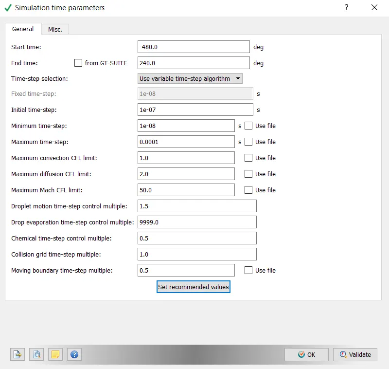
As a time we set crank angle to simulate the whole one cycle of the IC engine.
Boundary Conditions
Piston
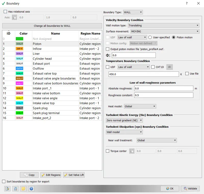
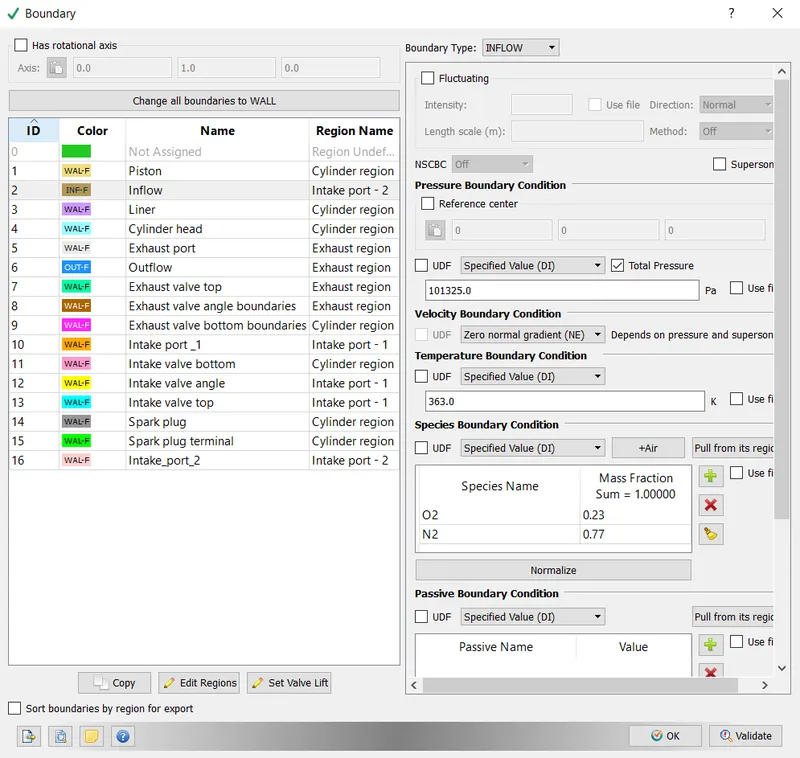
- Inflow
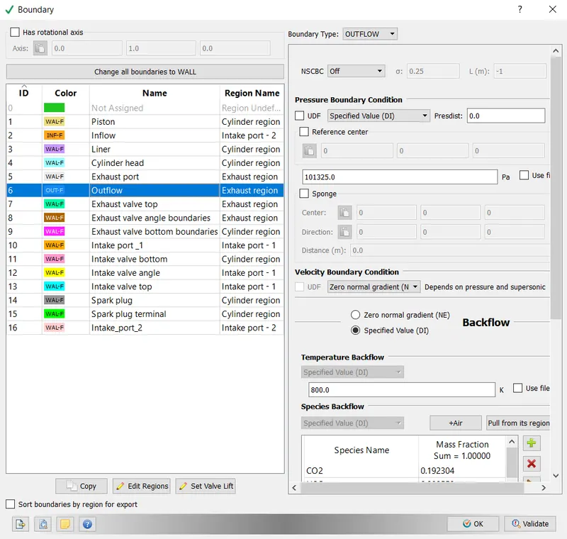
- Outflow
- Intake valve top, angle and bottom
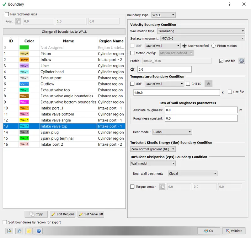
Intake valve top, angle and bottom are different surfaces with the exact same boundary conditions. Valve motion is defined using the provided file "intake_lift.in"
- Exhaust valve top, angle and bottom
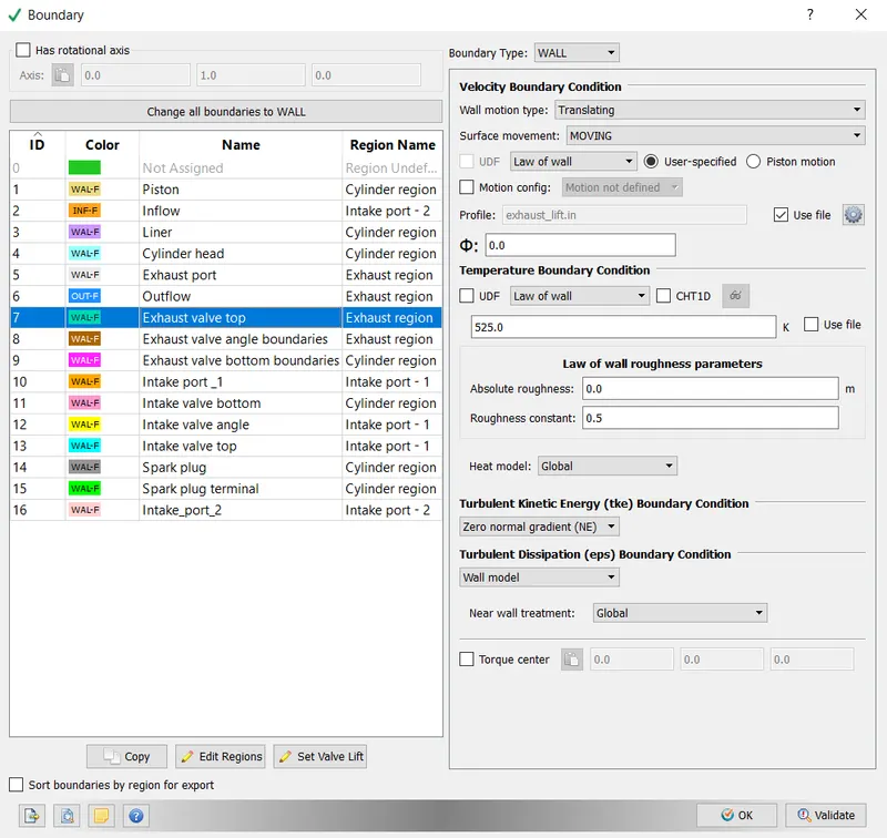
Exhaust valve top, angle and bottom are different surfaces with the exact same boundary conditions. Valve motion is defined using the provided file "exhaust_lift.in".
All other boundaries are the fixed wall boundaries, however the only difference is the Temperature boundary condition.
- Liner - 450K
- Cylinder head - 450K
- Exhaust port - 500K
- Intake port_1 - 425K
- Intake port_2 - 425K
- Spark plug - 550K
- Spurk plug terminal - 600K
As a fuel we use liquid Isooctane (IC8H18)
- Stoichiometric calculatior
For the combustion of our fuel we have an equation 1.
1)
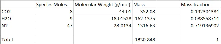
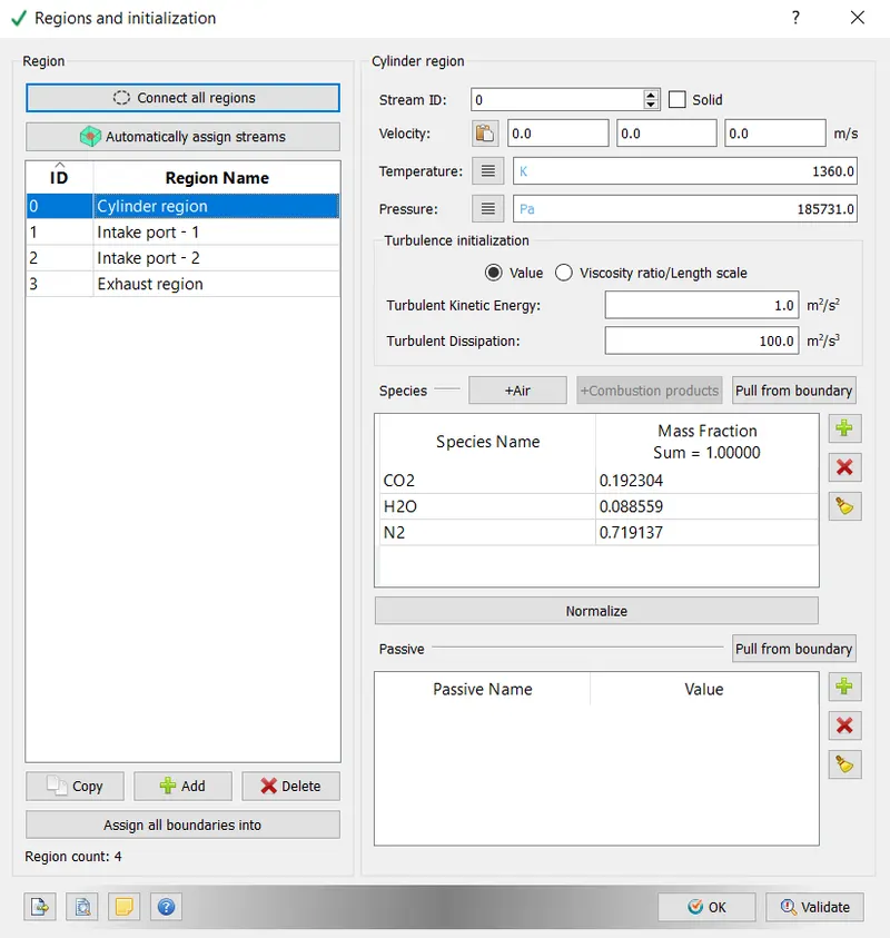
- Initial Conditions and Events
Cylinder region
Intake port - 1
Intake port - 2
Exhaust region
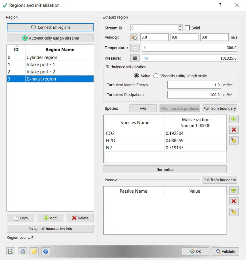
- Events
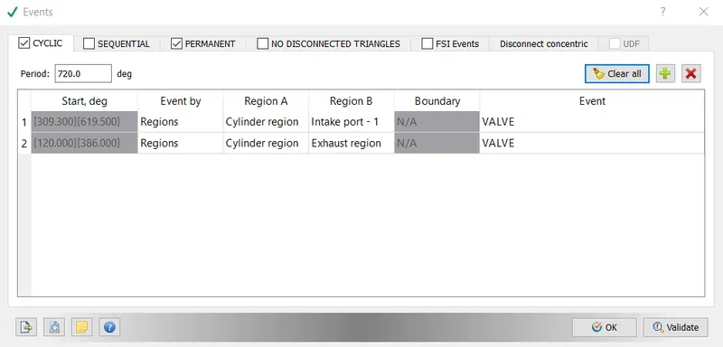
In the event above we see that cylinder ragion is connected with the Intake port - 1 and Exhaust region during the spacific range of crank angle.
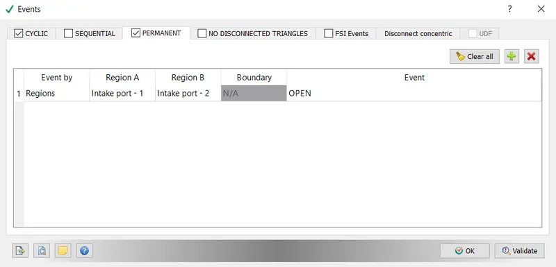
Intake port - 1 and Intake port - 2 are always open to each other.
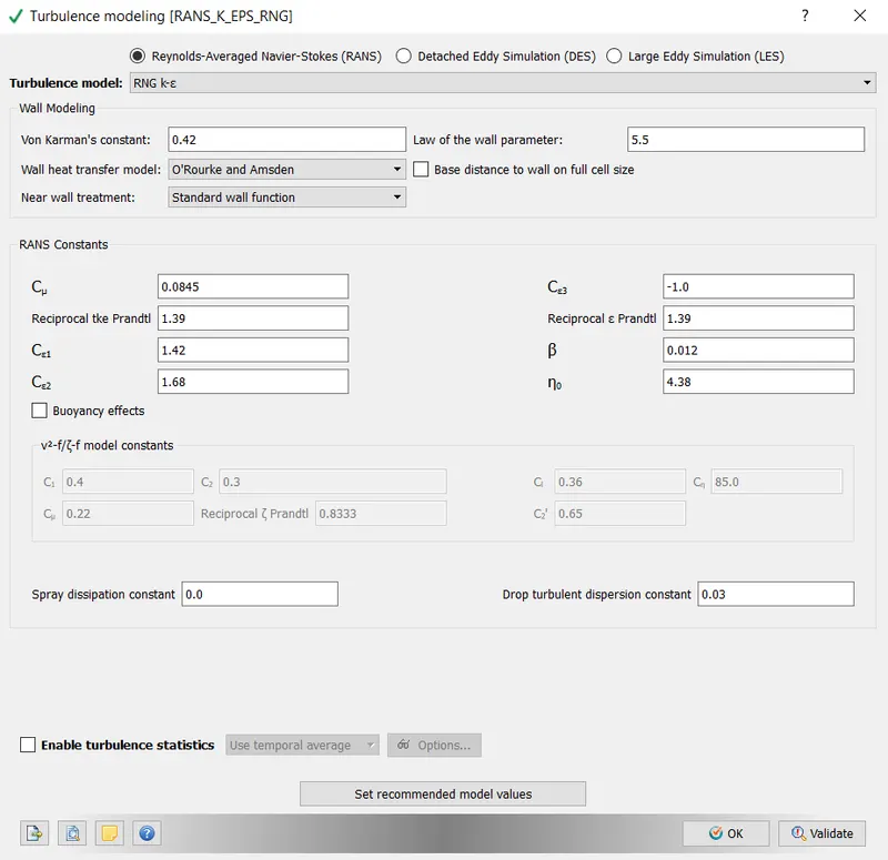
- Turbulence model
- Base grid
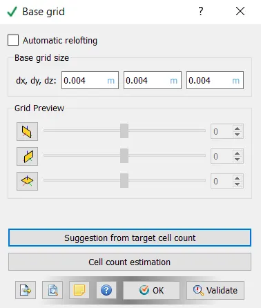
As we intend to simulate NO HYDRO in this challenge we just set base grid size to be 4mm in order to simulate the case faster. we dont use fixed embedding or AMR in this chapter of the project. Mesh will be refined in the FULL HYDRO case.