Week 3 - Pitot tube
Week 3 - Pitot tube
1. A pitot static tube geometry is attached below.
a.You are required to do a literature review of pitot-static tube. Also establish a relationship between Total (stagnation) pressure and static pressure
b.You are required to create surfaces and fill it separately for Total pressure port and static pressure port as shown below.
2. For the values of velocity given below calculate the total and static pressures and find the error in percentage for velocity.
|
Velocity(m/s) |
Gauge Pressure (Pa) |
|
240 |
-2817 |
|
100 |
33287 |
|
62 |
65780 |
ANSWERS
Aim: To perform simulation on the pitot tube using Ansys
A pitot tube, also known as pitot probe, is a flow measurement device used to measure fluid flow velocity. It is widely used to determine the airspeed of an aircraft, water speed of a boat, and to measure liquid, air and gas flow velocities in certain industrial applications.
The basic pitot tube consists of a tube pointing directly into the fluid flow. As this tube contains fluid, a pressure can be measured; the moving fluid is brought to rest (stagnates) as there is no outlet to allow flow to continue. This pressure is the stagnation pressure of the fluid, also known as the total pressure or (particularly in aviation) the pitot pressure.
The measured stagnation pressure cannot itself be used to determine the fluid flow velocity (airspeed in aviation). However, Bernoulli's equation states:
Stagnation pressure = static pressure + dynamic pressure
The dynamic pressure, then, is the difference between the stagnation pressure and the static pressure. The dynamic pressure is then determined using a diaphragm inside an enclosed container. If the air on one side of the diaphragm is at the static pressure, and the other at the stagnation pressure, then the deflection of the diaphragm is proportional to the dynamic pressure.
In aircraft, the static pressure is generally measured using the static ports on the side of the fuselage. The dynamic pressure measured can be used to determine the indicated airspeed of the aircraft. The diaphragm arrangement described above is typically contained within the airspeed indicator, which converts the dynamic pressure to an airspeed reading by means of mechanical levers.
Instead of separate pitot and static ports, a pitot-static tube (also called a Prandtl tube) may be employed, which has a second tube coaxial with the pitot tube with holes on the sides, outside the direct airflow, to measure the static pressure.
Simulation
Solver: Pressure Based
Simulation: Steady State
Material: Air
Viscous Model: Laminar
Boundary Conditions:
|
Velocity(m/s) |
Gauge Pressure (Pa) |
|
240 |
-2817 |
|
100 |
33287 |
|
62 |
65780 |
Case 1
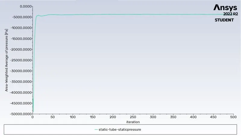
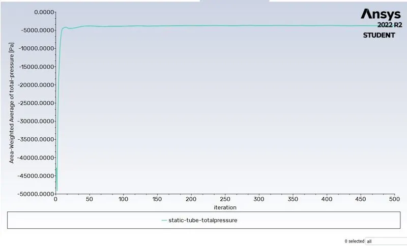
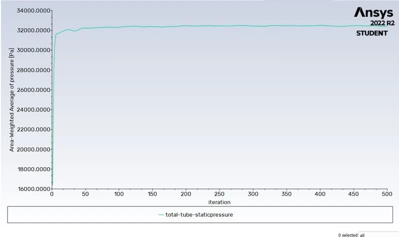
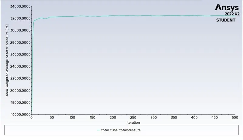
Velocity = 240 m/s
Gauge Pressure = -2817 Pa
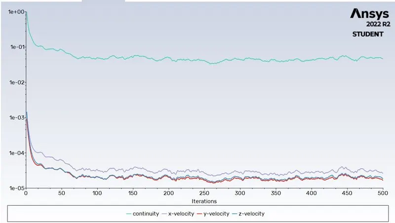
Residuals
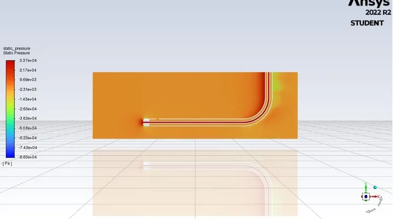
Static Pressure Contour
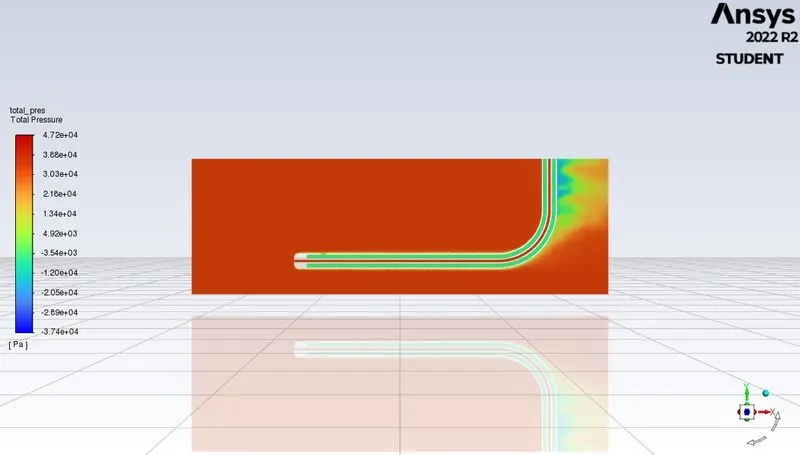
Total Pressure Contour
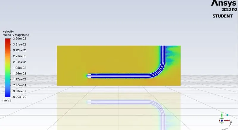
Velocity Magnitude Contour
Plot for the Static Pressure of the Static Tube
Plot for the Total Pressure of the Static Tube
Plot for the Static pressure of the Total Pressure Tube
Plot for the Total Pressure of the Total Pressure Tube
Case 2
Velocity = 100 m/s
Guage Pressure = 33287 Pa
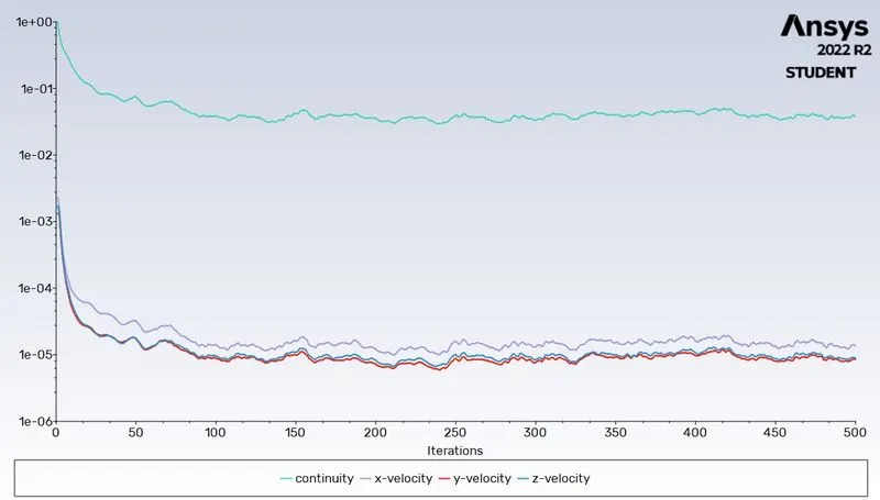
Residual Plot
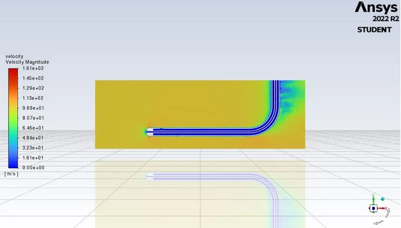
Velocity Magnitude Contour
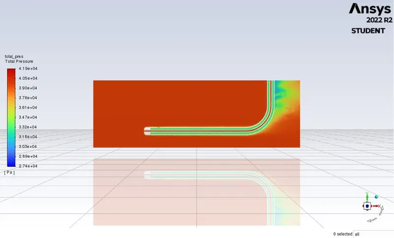
Total Pressure Contour
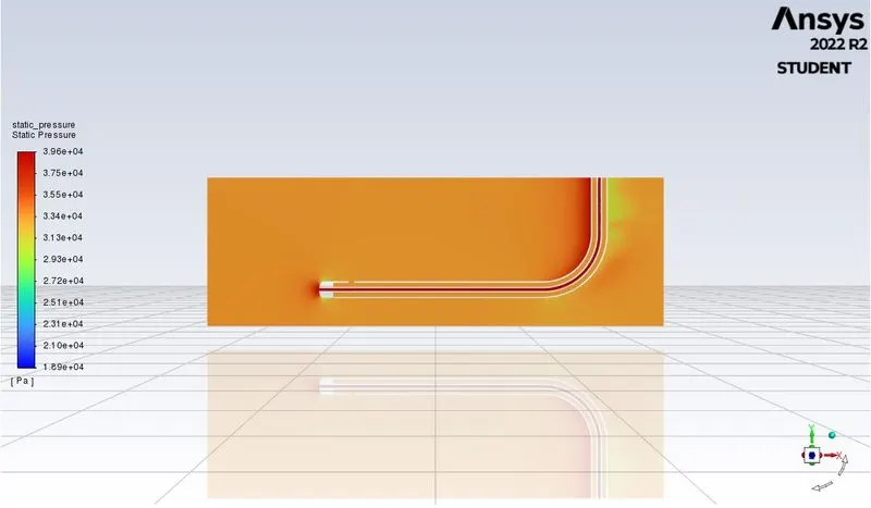
Static Pressure Contour
Plot for the Total Pressure of the Total Tube
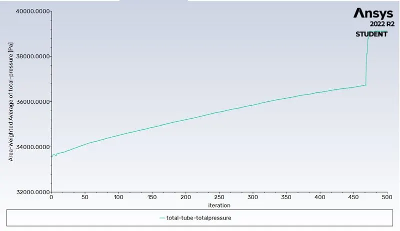
Plot for the Static Pressure of the Total Tube
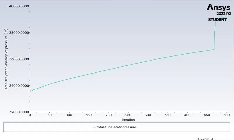
Plot for the Total Pressure of the Static Tube
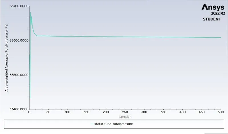
Plot for the Static Pressure of the Static Tube
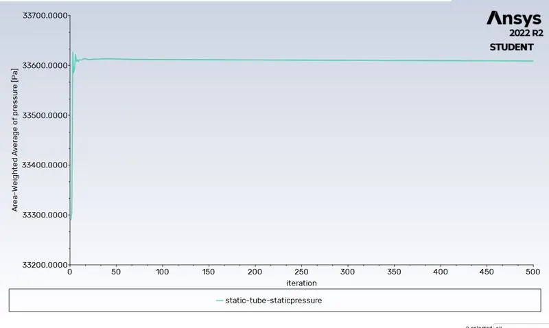
CASE 3
Velocity = 62m/s
Guage Pressure = 65780 Pa
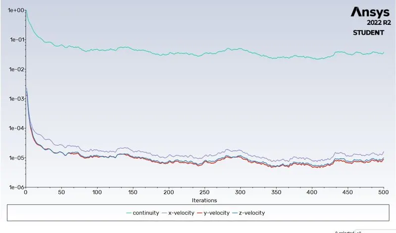
Residual Plot
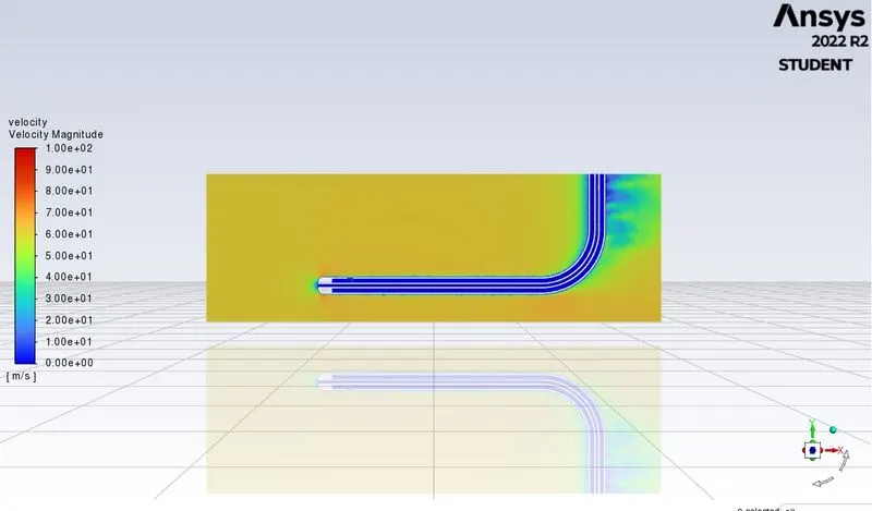
Velocity Magnitude Contour
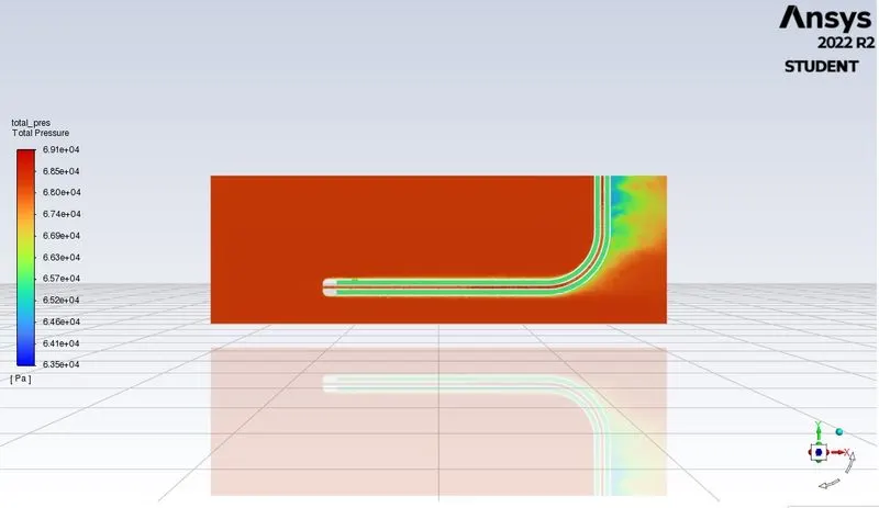
Total Pressure Contour
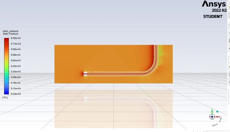
Static Pressure Contour
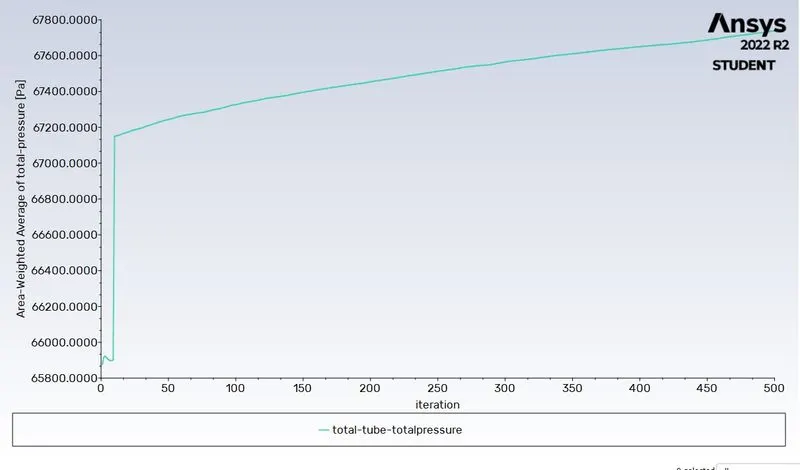
Plot for the Total Pressure of the Total Tube
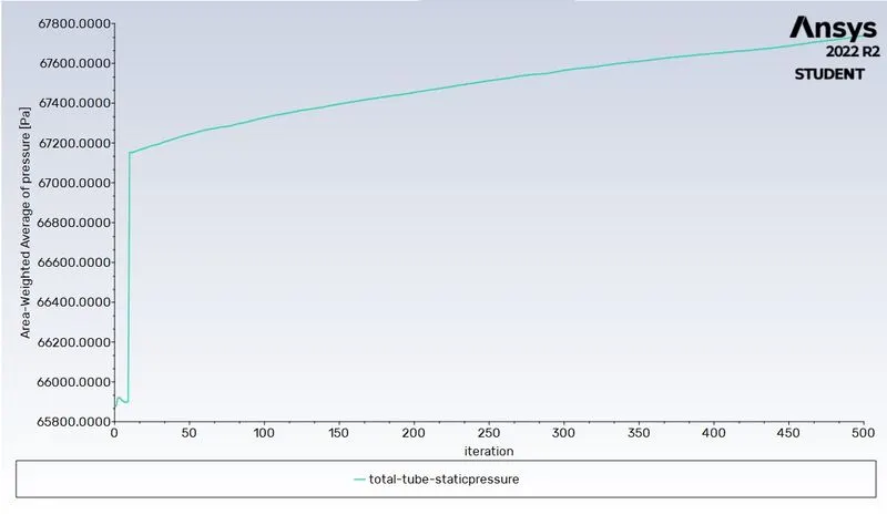
Plot for the Static Pressure of the Total Tube
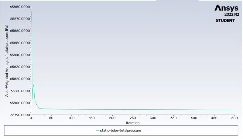
Plot for the Total Pressure of the Static Tube
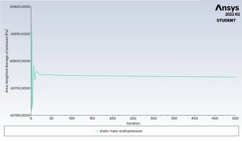
Plot for the Static Pressure of the Static Tube
Result Comparison
Static Pressure(Pa) Total Pressure(Pa) Velocity (m/s) Error(%)
-3574.3929 21997.782 226.16 5.76
33164.514 37615 94.344 5.56
65736.338 67449.93 58.54 5.58
conclusion
the pitot tube simulation is carried out with different velocities to predict the static and total pressure at outlet. The variation of error is marginal and lies within the acceptable region.