Week 8 - Simulating Cyclone separator with Discrete Phase Modelling
1. To write a few words about any four empirical models used to calculate the cyclone separator efficiency
Cyclone separators are separation devices that use the principle of inertia to remove particulate matter from flue gases. Cyclone separators is one of many air pollution control device known as pre-cleaners since they generally remove larger pieces of particulate matter. This prevents finer filtration methods from having to deal with large, more abrasive particles later on. in addition, several cyclone separators can operate in parallel, and this system is known as a multi cyclone.
It is important to note that cyclones can vary drastically in their size. The size of the cyclone depends largely on how much flue gas must be filtered, thus larger operations tend to need larger cyclones. For example, several different models of one cyclone type can exist, and the size can range from a relatively small 1.2-1.5 meters to around 9 meters.
Applications
Sawmills to remove sawdust
Oil Refineries
kiln preheaters
Vacuum Cleaners
Extraction Hoods
Efficiency
They can generally remove somewhere between 50-99% of all particulate matters in the flue gas. How well the cyclone separators are actually able to remove this matter depends largely on particle size. If there is a large amount of lighter particulate matter, fewer of these particles are able to separate out, because of this, cyclone separators work best on flue gases that contain large amounts of big particulate matter.
2. To perform an analysis on a given cyclone separator model by varying the particle diameter from 1 μm to 5 μm and calculate the separation efficiency in each case. Discuss the results. [Use both the velocity's as 3m/sec.]
CASE -1
***We use the element size = 20mm throughout for all the 3 cases***
Particle Diameter = 1 Picometer
Geometry
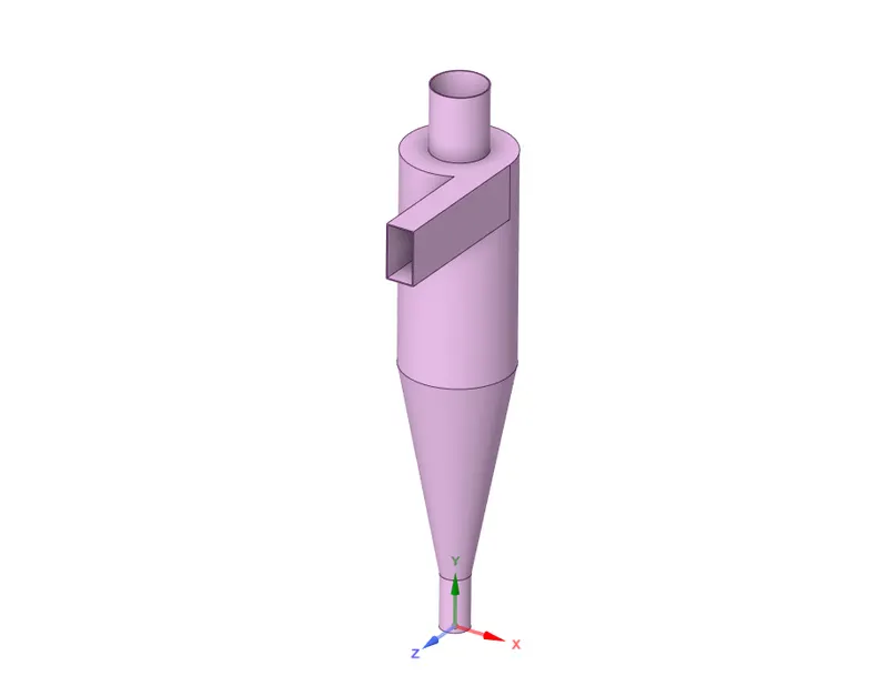
This is the geometry of the cyclone separator, to do the analysis.
First, we need to extract the fluid volume and suppress for physics the original body.
Open Mesh
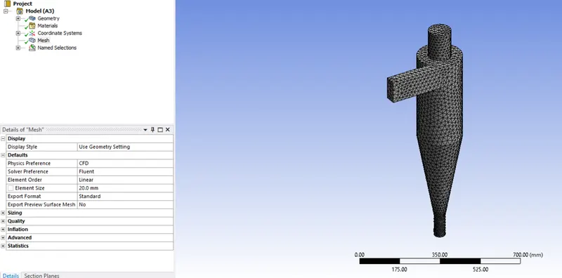
Mesh it for 20mm element size.
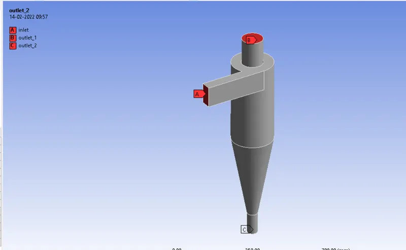
create named selections for Inlet, Outlet_1, and Outlet_2
Open Setup
Enable gravity in the Y direction.
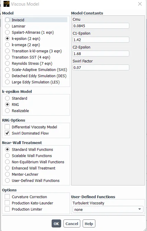
Set the viscous model as k-Epsilon
Now, open Discrete Phase Model (DPM)
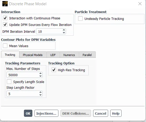
Enable interaction with continuous phase and Update DPM sources every flow Iteration
and open Injections Box
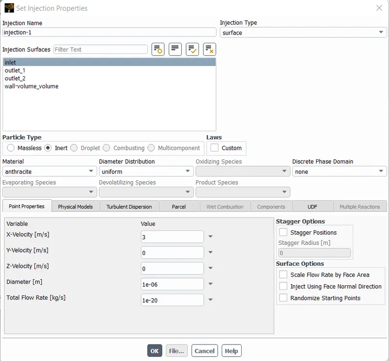
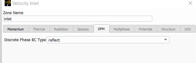
Now, open boundary conditions
for inlet, set velocity = 3m/s and in DPM tab choose reflect.
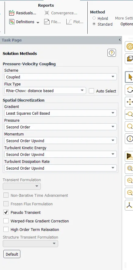
In Solution methods, select accordingly.
Initialize it and run the simulation for 600 iterations
Results
Residual Plot.
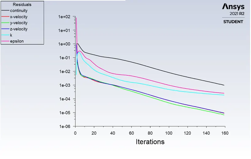
Now we export the file from setup and save it to our PC.

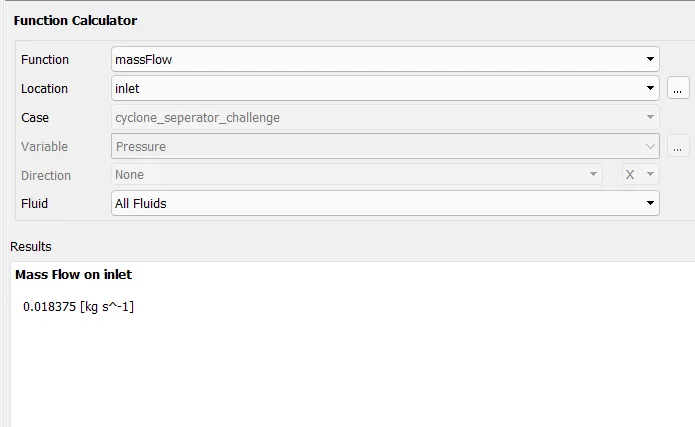
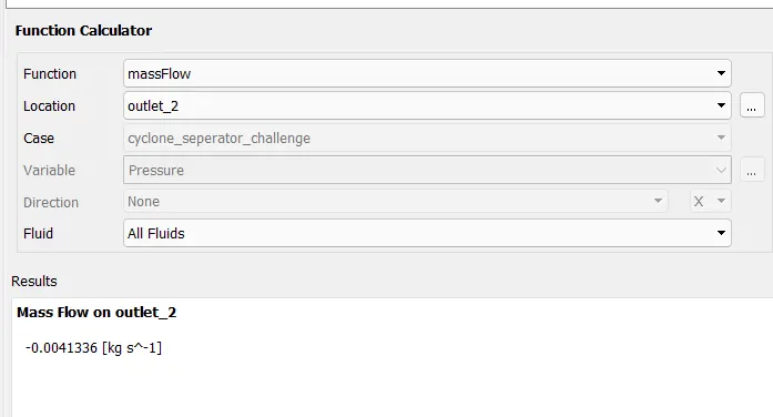
Here all the particles have escaped through the outlet, therefore we can say that the efficiency here is 100%.
Now open Results
Load the file from our PC
Choose the variable as Anthracite Particle. Time
and Set it accordingly.
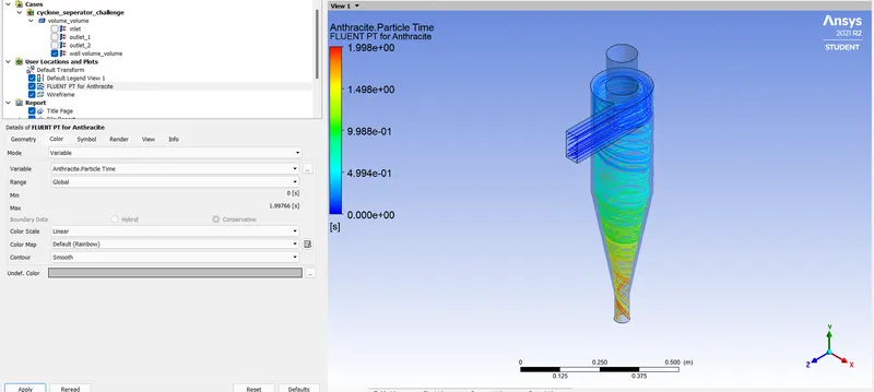
Inlet Mass Flow
Outlet Mass Flow.
CASE - 2
Particel Diameter = 3 picometer
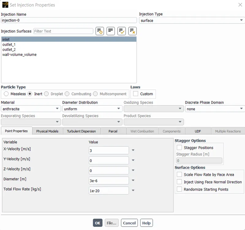
here we use 3 picometer particle diameter and 3 meter/sec velocity
All the other settings are the same as the previous one and do simulation for 600 iterations
Results
Residuals Plot
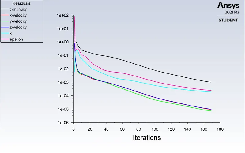

here also we can say that the efficiency is 100%, because all the particles entered have exited completely.
Post Results
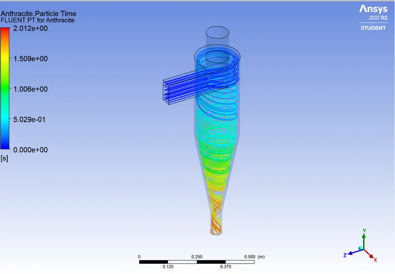
The vortex contour
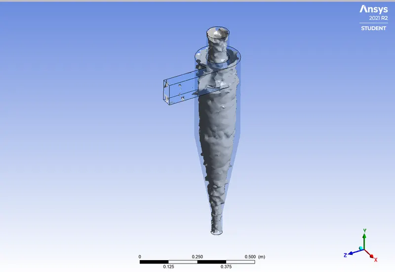
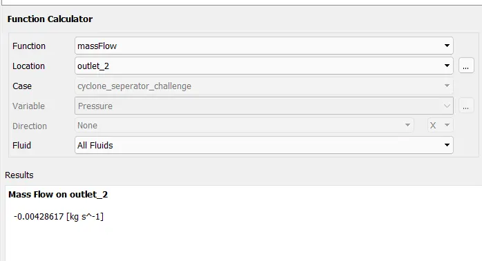
Calculated Mass flow rate at outlet
CASE-3
Particle diameter = 5 Picometer
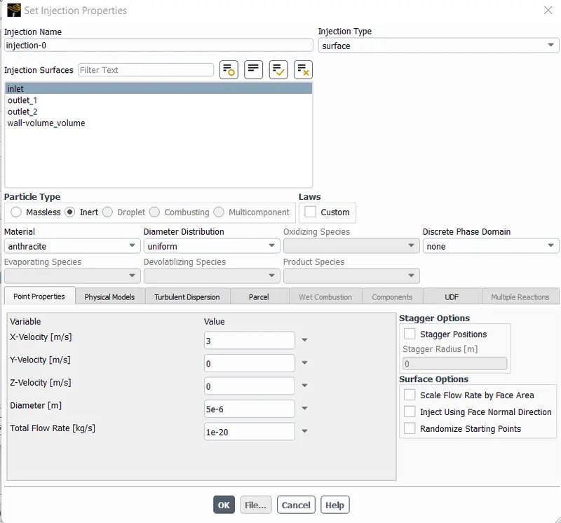
Here the particle diameter is set to 5 picometers.
and we run the simulation for 600 iterations.
The obtained Residual Plots.
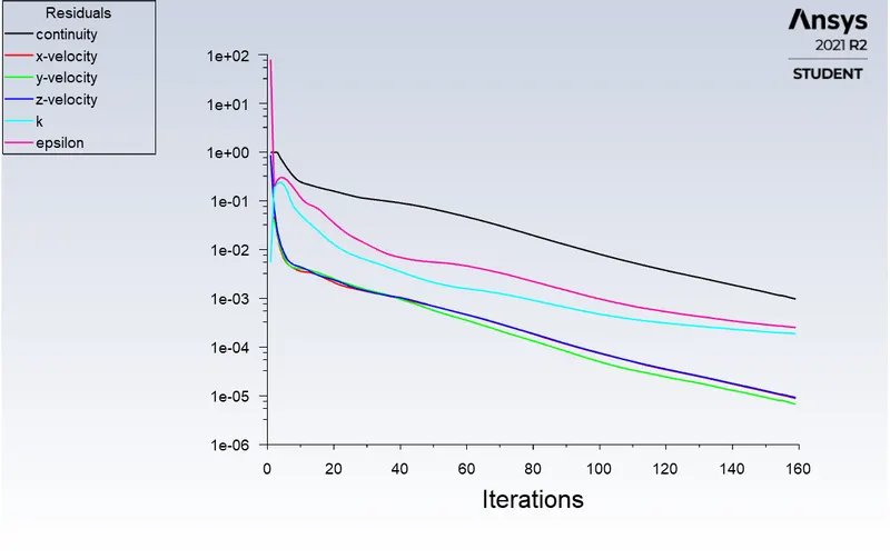
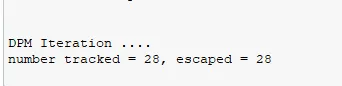
here also the efficiency obtained is 100%.
Open Post Results
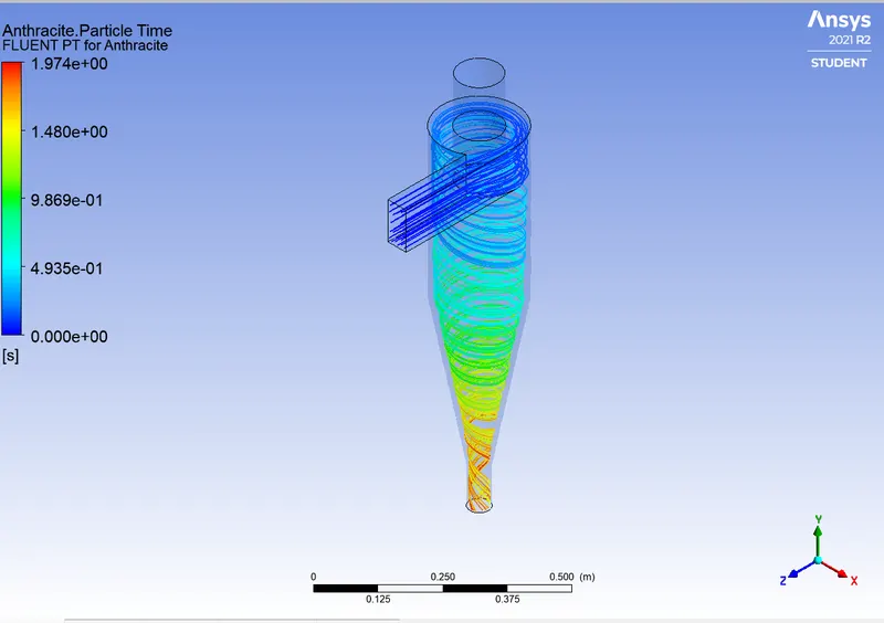
The time contour of the particle.
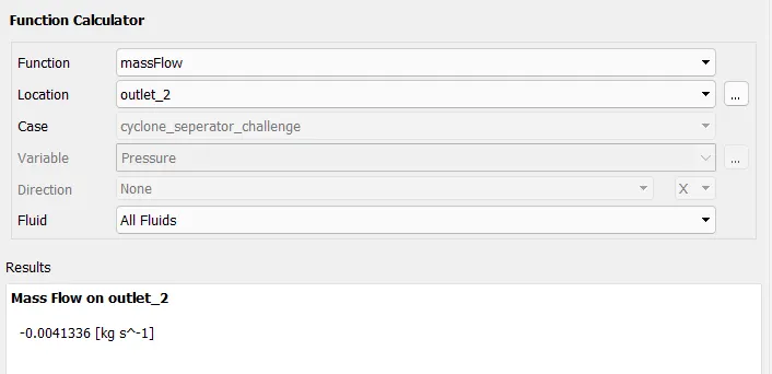
the mass flow rate at the outlet is
3. To perform an analysis on a given cyclone separator model by varying the particle velocity from 1 m/sec to 5 m/sec and calculate the separation efficiency and pressure drop in each case. Discuss the results. [Use particle diameter size as 5 μm for all cases & keep flow velocity same as particle velocity]
**Here we use a Particle diameter is 5 picometers throughout, and we adjust velocities for different cases**
CASE -4, Velocity = 1 m/s
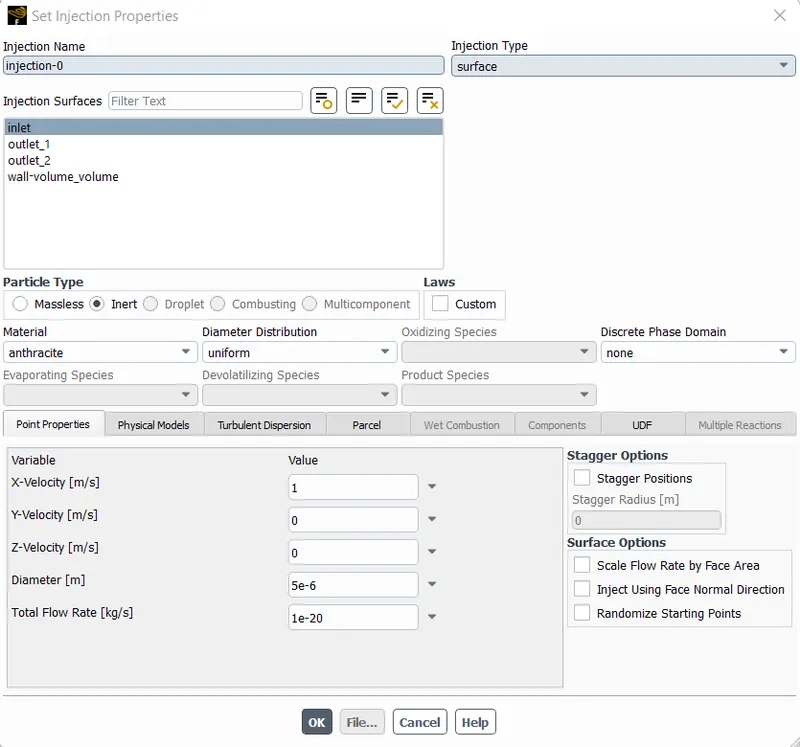
here we put the velocity = 1 m/s
On doing the simulation for 600 Iterations
The Residual Plot is
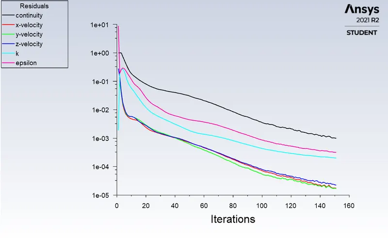
here also the efficiency is showing 100%.
Now open CFD Post
The particle Time contour is shown
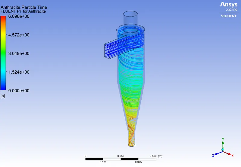
The Mass flow rate at the outlet is shown
CASE -5
Velocity = 3m/s
Editing the DPM for 3m/s
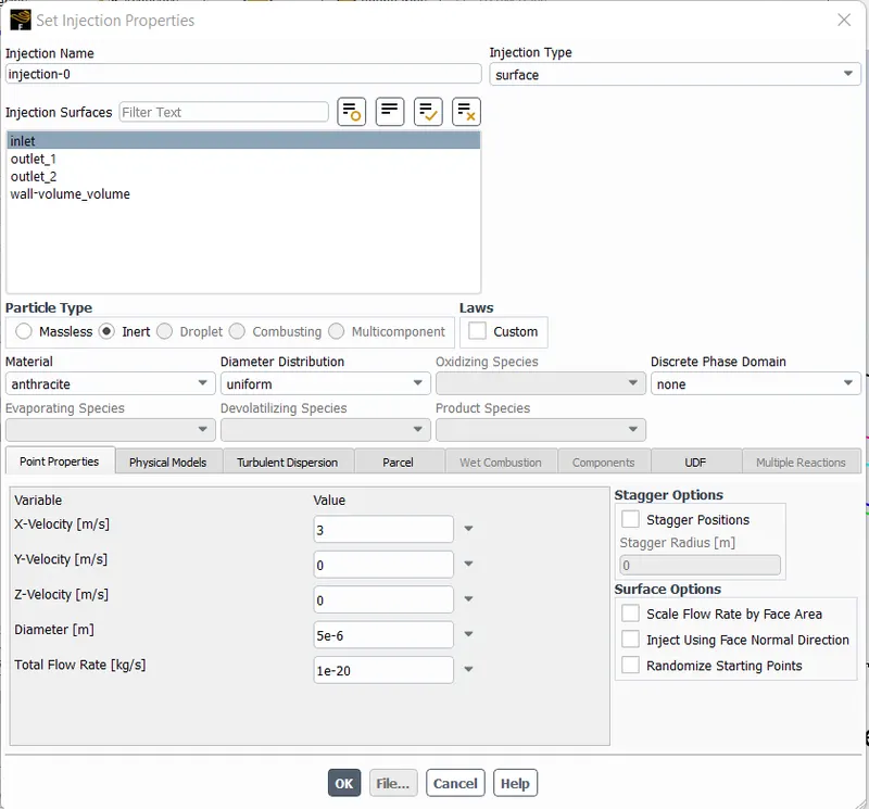
After completing the iterations for 600 times
The result obtained
The Residuals Plot
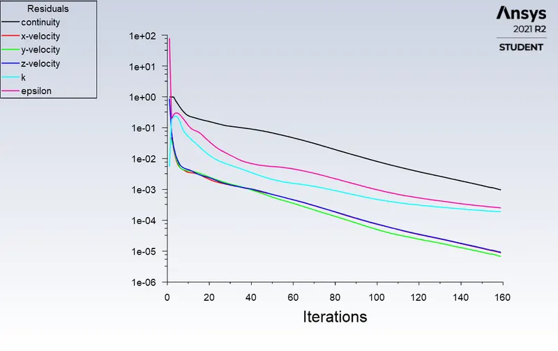
Here too the efficiency is 100%.
Opening CFD Post
The Particle Time contour
The Mass flow at the outlet
CASE -6
Velocity - 5m/s
setting velocity as 5 m/s
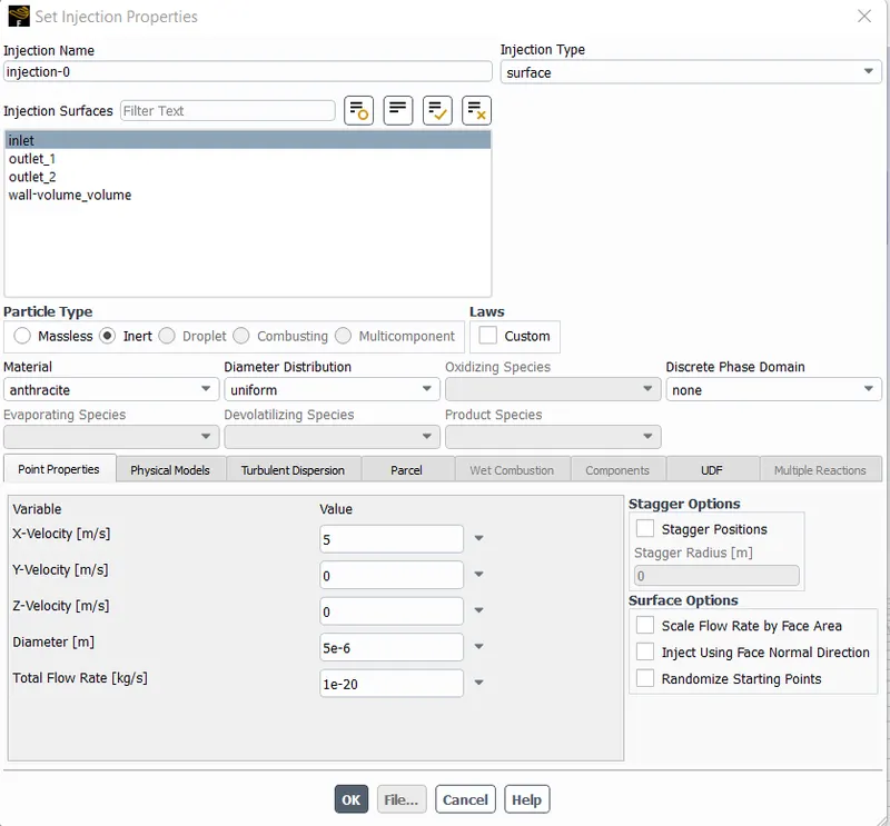
Here also the efficiency is 100%
after completeing 600 Iterations
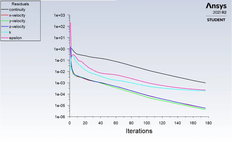
The Residual plot
Opening CFD Post
Time contour of particles
The mass flow at the outlet is shown
Conclusions
The separator efficiency depends on the particle size.
An increase in velocity causes the pressure drop to rise exponentially.
Velocity has a higher impact as compared to the diameter of the particle.
Here is a link to a video of case 1