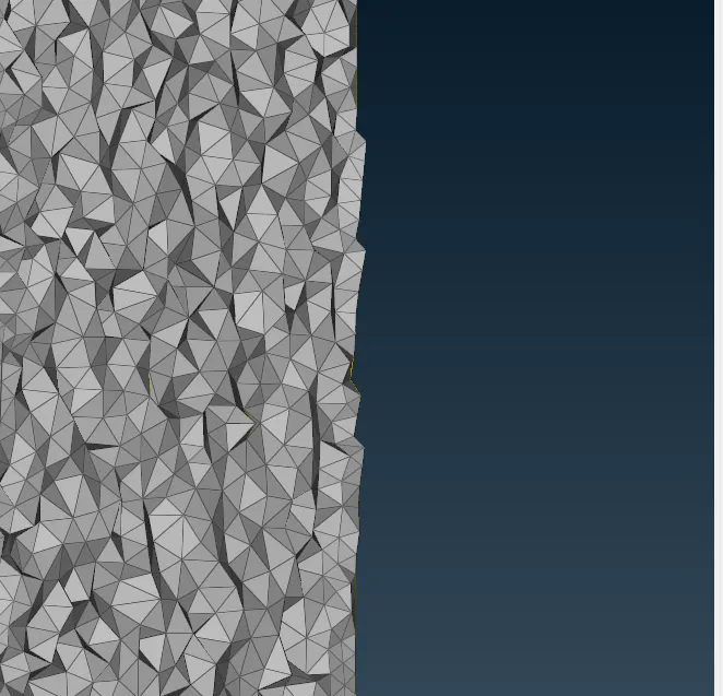
Week 3 Challenge : CFD meshing on Turbocharger
Objective
For the given model, check for the geometrical errors to make appropriate volumes. Create and assign PIDs as shown in the video. Perform surface mesh with the given target lengths as per PIDs.
- Blade stage-1 = 1 mm
- Blade stage-2 = 1 mm
- Impeller = 2 mm
- Shaft rotor = 1 mm
- Turbo casing = 5 mm
- Compressor casing = 5 mm
- Inlet casing cover = 5 mm
Answer
The Geometry
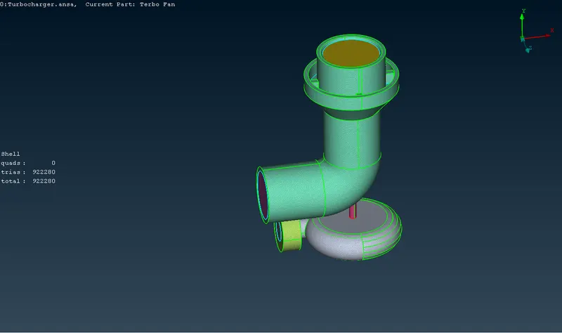
The given geometry is a 3D figure of a turbocharger and we need to pre-process the file and finally mesh it.
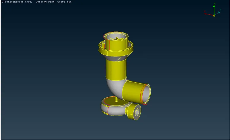
Firstly, enable the PID view and delete the overlapped (pink color) surface from it.
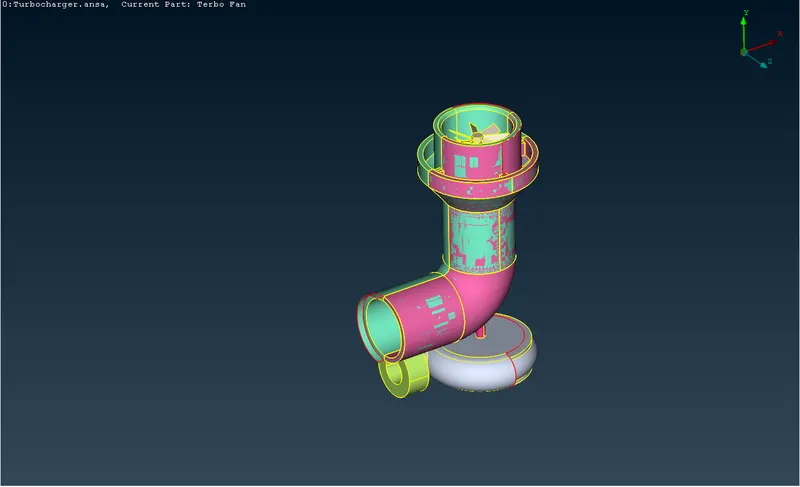
Then we will get a clean file free from the overlapped surfaces.
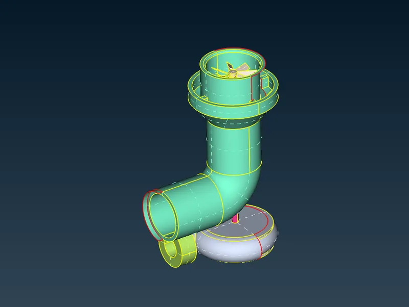
Add new surfaces where ever the surfaces or body are not present.
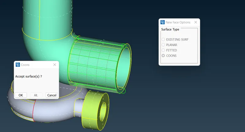
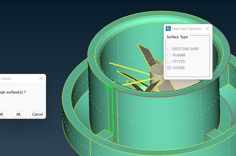
At the top too.
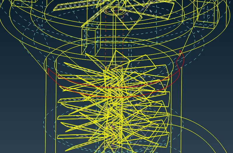
Enable the wire frame view to check for any con errors. Here we saw that there is a single con surface and it need to be refined.
By selecting the intersecting option, select the two faces which need to intersect at a junction.
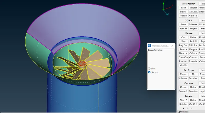
and finally, delete the existing surface.
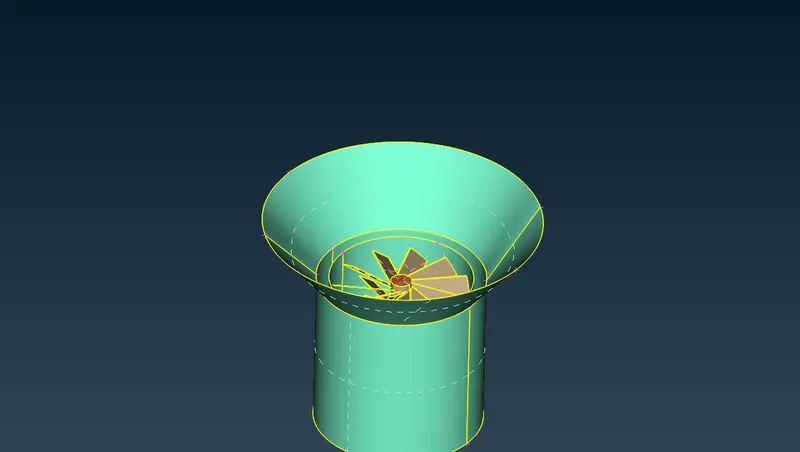
And finally, there is a region at the bottom, which needs to be filled with the surface.
for this several hot points are created at the boundary of the edge for creating smooth surfaces.
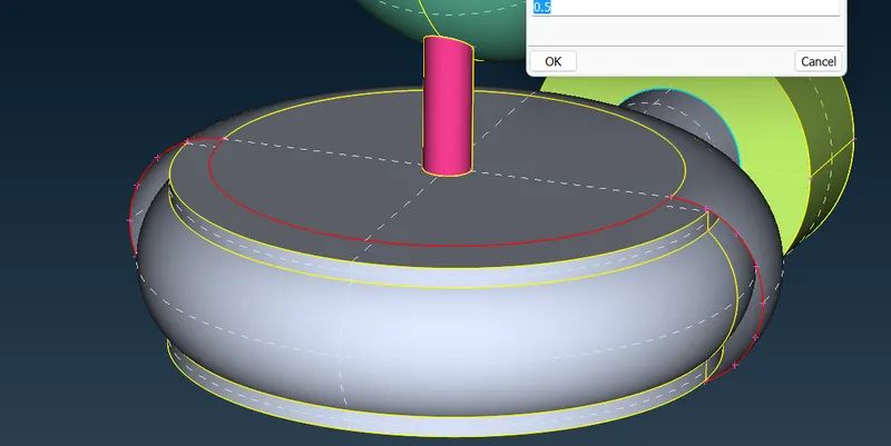
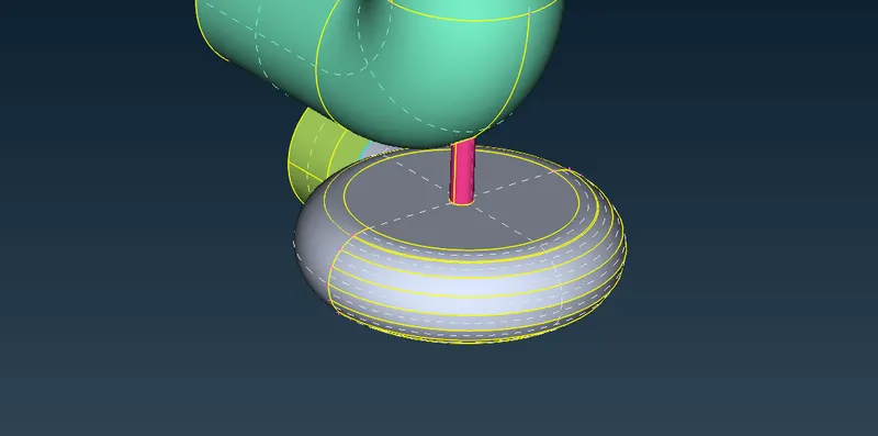
Like wise the hole is filled with new surface.
Now, we need to check for the quality of the file for which what we had done so far.
here we find two single con errors. The remaining two triple cons errors is acceptable, since it does not harm or meshing.
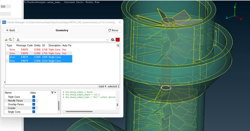
Here, we can see an overlapped surface on the shaft. To delete this, we need to create a new edge at the region and delete the remaining part.
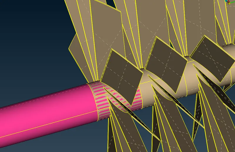
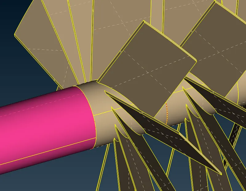
After doing above corrections, we can see that our selected geometry is corrected with no errors (Shaft)

Now, next we need to do is that to fill all the holes at every surface to get a closed geometry for meshing.
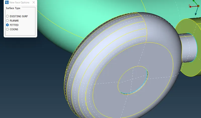
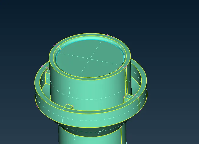
Meshing
Starting to mesh the geometry with above-listed prerequisites.
That is
- Blade stage-1 = 1 mm
- Blade stage-2 = 1 mm
- Impeller = 2 mm
- Shaft rotor = 1 mm
- Turbo casing = 5 mm
- Compressor casing = 5 mm
- Inlet casing cover = 5 mm
For 5 mm Mesh size.
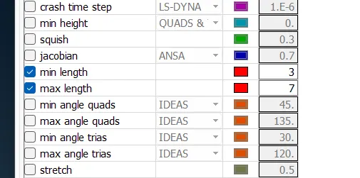
For the first, the outer geometry and its related components are meshed with element size of 5mm.
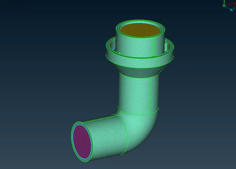
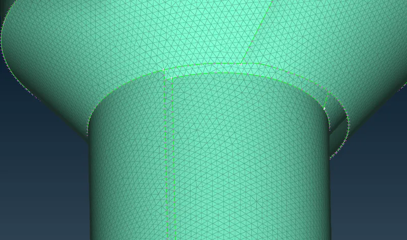
Turbo casing is also meshed for 5mm.
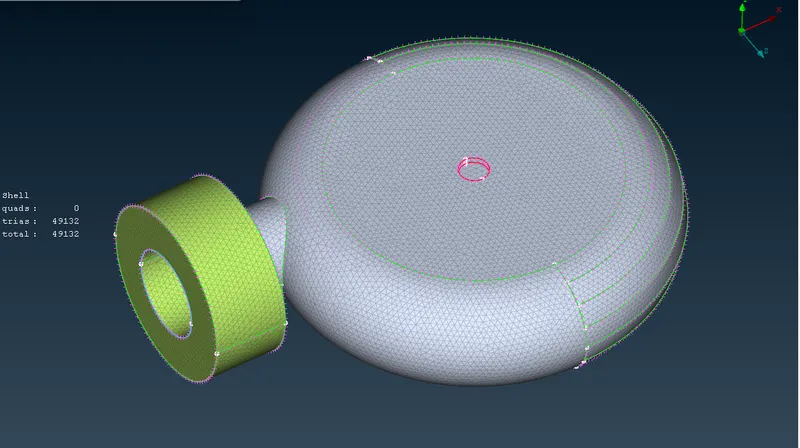
Now, the impeller is meshed for 2mm size.
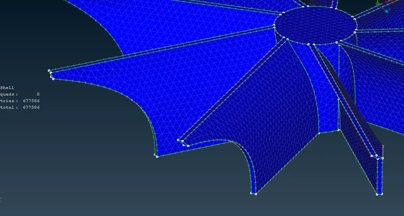
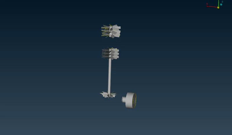
Blade stage 1 and Blade stage 2 is meshed for 1mm size.
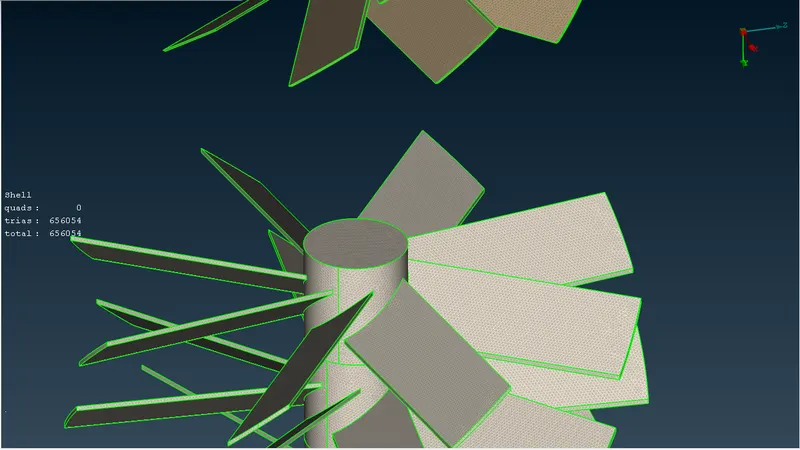
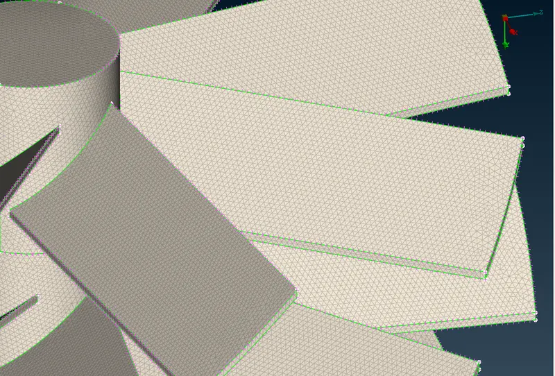
The rotor shaft is also meshed for 1mm size.
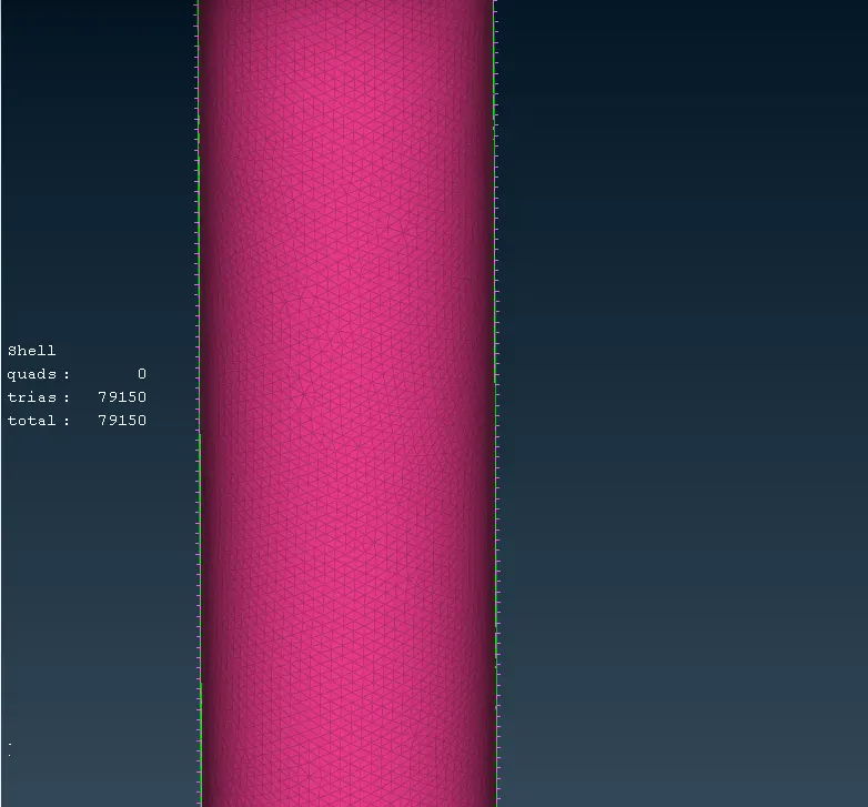
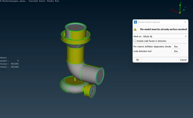
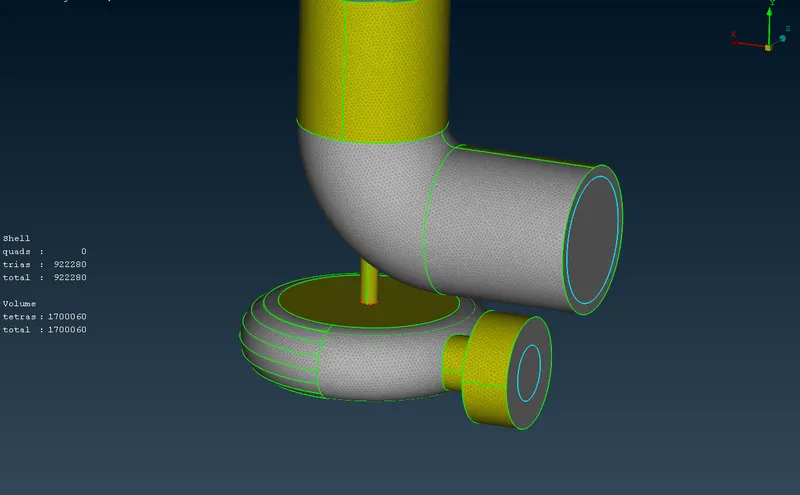
Completely meshed geometry.
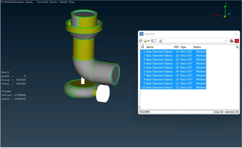
Volume Meshing
All the PIDs mesh under volume meshing. Tetra CFD meshing is done for it.