Week-7 : Converting a detailed engine model to a FRM model
Aim:
- To Explore tutorial number 9 and write a detailed report (50 marks)
- To Build FRM Model for following configuration using FRM builder approach (50 marks)
- Bore 102 mm stroke 115 mm CR 17
- No of cylinder 6
- CI engine
- Twin Scroll Turbine
- GT Controller
Introduction:
FRM is a physical engine model that is designed specifically to run fast.When simulation speed is of high priority then GT power engine models can be simplified into FRM's using a standard conversion process.
FRMs can be achieved by two means,
- Decreasing the simulation time step size
- Decreasing the sub volume
Q:-Explore tutorial number 9 and write a detailed report (50 marks)
Ans:-
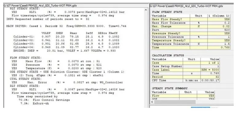
Tutorial 9 shows the case setup given below is GDI SI engine FRM Model. It is Gas direct injection model inwhich fuel is injected into comsution chamber during compression Stroke to make Homogenous mixture. It is fast running model so give quick result of case setup.
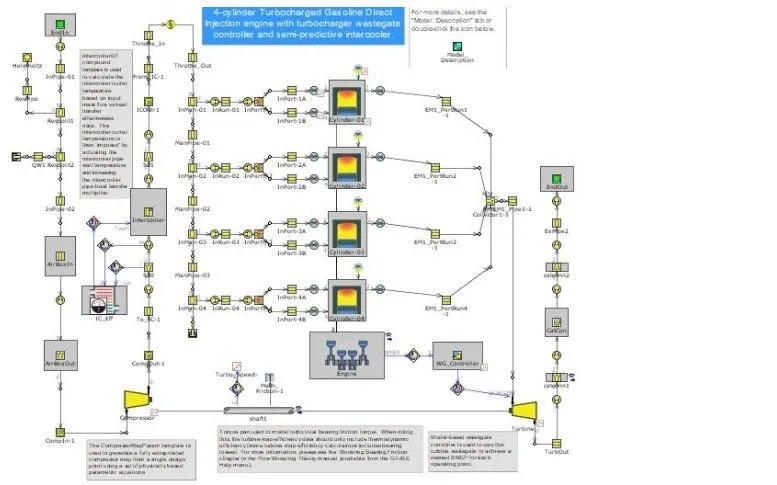
The inlet air at ambient temperature and pressure passes through air Box and enter into compressor and air is compressed to increase boost pressure and goes into combustion chamber through individual inlet manifold.
The processing time of case setup are given below.
CPU time:- 50:17
Time :- 0.768
It is fast running model.
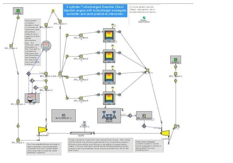
This model is DI Diesel Model in which air from Ambient air enter into Compressor which increase air temperature and pressure. Air then enter into intercooler which cool charge air and increase density of air. Air then enter into single inlet manifold and then into combustion chamber.
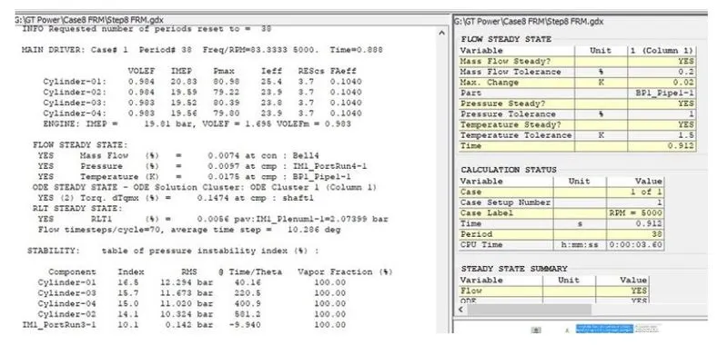
The processing time is very less so can run many cases in less time as shown below.
CPU time:- 3:60
Time:- 0.912sec
Question:- Build FRM Model for following configuration using FRM builder approach (50 marks)
- Bore 102 mm stroke 115 mm CR 17
- No of cylinder 6
- CI engine
- Twin Scroll Turbine
- GT Controller
Answer:-
FRM builder are used to create quick Engine Model with less input data as shown below. FRM represent about fast Running Model in which processing time of case setup is reduced and it give quick result.
Below Engine model are 6 Cylinder CI Engine with engine geometery
Bore = 102mm
Stroke =115mm
CR= 17
It is having Turbocharger with twin scroll turbine in which exhaust from three cylinder head goes into seperate passage into turbocharger to avoid pulse generation.Then exhaust passes though aftertreatment System and goes into enviroment.After Treatment system reduce emmission as per emmission Norms.
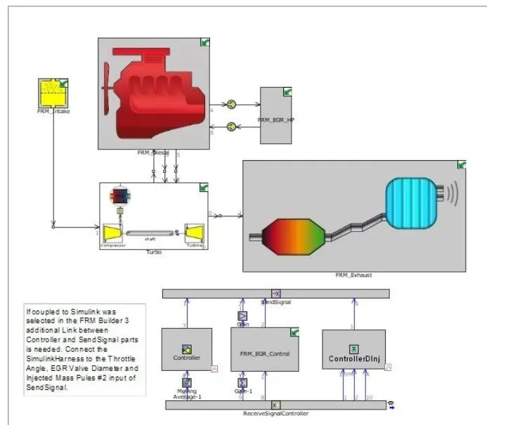
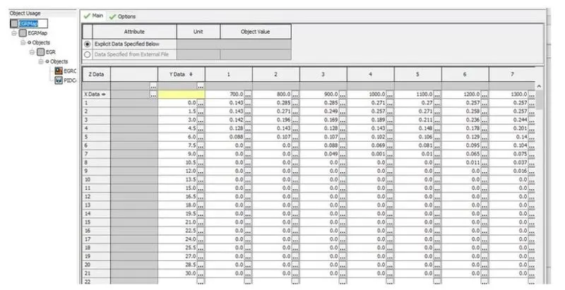
it has controllers to control engine management system as shown above like EGR control,BMEP controller and boost pressure controller.EGR control controller in this case is closed loop controller as shown below in which on X-axis input parameter is RPM and on Y axis input parameter is Target Bmep and EGR value opening is according to these parameters.
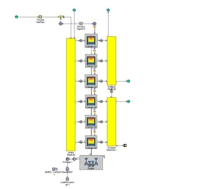
The Main Body as shown below in which inlet manifold and exhaust manifold with twin scroll entery into turbine are given below.
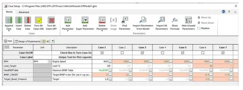
Run case setup with Engine speed ,Required BMEP and Target Boost Pressure as shown below.
The geometry parameters are given below
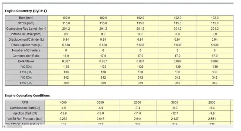
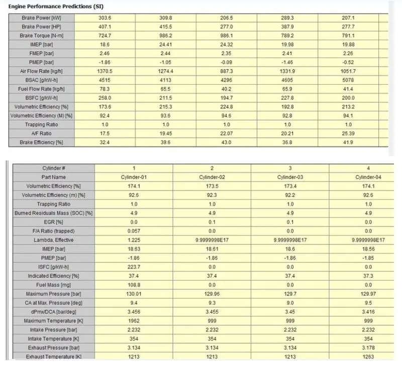
The output parameter are shown below.
Brake Power 303.6 KW
Brake Torque = 714 Nm
Air flow rate= 1370.5 kg/Hr
Thank You