Simulating Cyclone separator with Discrete Phase Modelling
AIM:
To learn setting up a discrete phase modeling case in ANSYS Fluent. To calculate the efficiency of the given cyclone geometry. To analyze total erosion on the separator’s surface due to the particles.
INTRODUCTION:
A cyclonic separation is a method of removing particulates from an air, gas or liquid stream, without the use of filters, through vortex separation. When removing particulate matter from liquid, a hydro-cyclone is used; while from gas, a gas cyclone is used. Rotational effects and gravity are used to separate mixtures of solids and fluids. The method can also be used to separate fine droplets of liquid from a gaseous stream. A high-speed rotating (air)flow is established within a cylindrical or conical container called a cyclone. Air flows in a helical pattern, beginning at the top (wide end) of the cyclone and ending at the bottom (narrow) end before exiting the cyclone in a straight stream through the center of the cyclone and out the top. Larger (denser) particles in the rotating stream have too much inertia to follow the tight curve of the stream, and thus strike the outside wall, then fall to the bottom of the cyclone where they can be removed. In a conical system, as the rotating flow moves towards the narrow end of the cyclone, the rotational radius of the stream is reduced, thus separating smaller and smaller particles.
The cyclone geometry, together with volumetric flow rate, defines the cut point of the cyclone. This is the size of particle that will be removed from the stream with a 50% efficiency. Particles larger than the cut point will be removed with a greater efficiency, and smaller particles with a lower efficiency as they separate with more difficulty or can be subject to re-entrainment when the air vortex reverses direction to move in direction of the outlet. This report is divided in 4 parts:
1) Simulation of discrete phase modelling with 2 particles for 3 different types of mesh sizes.
2) Using different boundary conditions for inlet in a particular mesh from above case.
3) Calculation of efficiency of cyclone separator.
Some Scientific models used for efficiency calculations of cyclone separator are:
1) Iozia and Leith Model: Iozia and Leith logistic model is a modified version of Barth model, which is developed based on force balance. The model assumes that a particle carried by the vortex endures the influence of two forces: a centrifugal force Z and a flow resistance W. The collection efficiency of particle diameter can be calculated from: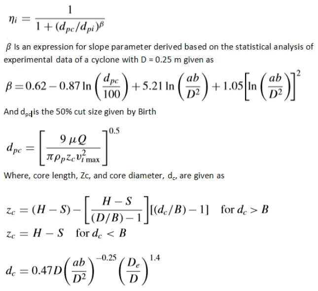
2) Li and Wang Model The Li and Wang model includes particle bounce or reentrainment and turbulent diffusion at the cyclone wall. A twodimensional analytical expression of particle distribution in the cyclone is obtained. Li and Wang model was developed based on the following assumptions: • The radial particle velocity and the radial concentration profile are not constant for uncollected particles within the cyclone. • Boundary conditions with the consideration of turbu185 lent diffusion coefficient and particle bounce reentrainment on the cyclone wall are: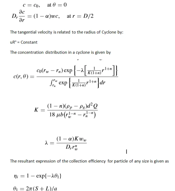
3) Koch and Licht Model Koch and Licht collection theory recognized the inherently turbulent nature of cyclones and the distribution of gas residence times within the cyclone. Koch and Licht described particle motion in the entry and collection regions with the additional following assumptions: • The tangential velocity of a particle is equal to the tangential velocity of the gas flow, i.e. there is no slip in the tangential direction between the particle and the gas. • The tangential velocity is related to the radius of cyclone by: u Rn = constant. A force balance and an equation on the particles collection yields the grade efficiency:
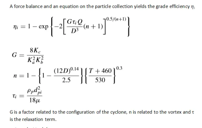
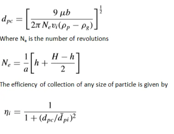
4) Lapple Model Lapple model was developed based on force balance without considering the flow resistance. Lapple assumed that a particle entering the cyclone is evenly distributed across the inlet opening. The particle that travels from inlet half width to the wall in the cyclone is collected with 50% efficiency. The semi-empirical relationship developed by Lapple to calculate a 50% cut diameter:
Part - 4: Erosion modelling The particles that revolve near to wall, collide with it and erode the surface. This causes reduction in thickness of cyclone separator wall. To find the erosion due to particles, this simulation is done using erosion models in ANSYS Fluent. The model chosen for this type of flow is Finnie model. This model is useful for erosion on ductile material where erosion varies with impact angle and velocity.
GEOMETRY USED
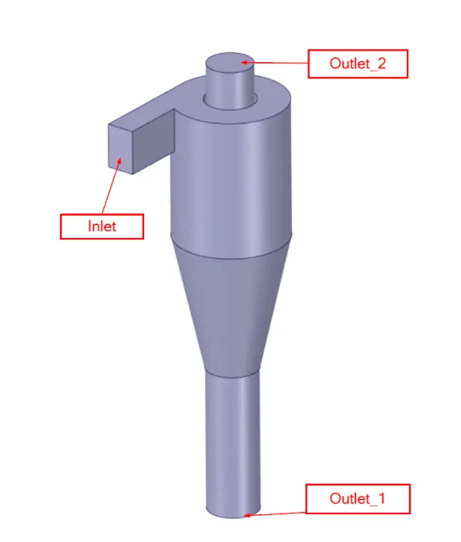
CYCLONE SEPARATOR GEOMETRY
This is the geometry model taken for simulation purpose. The fluid volume which is inside the separator is extracted and all other solid bodies are suppressed for further analysis.
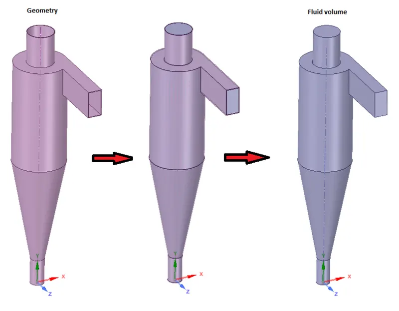
FLUID VOLUME EXTRACTION FROM GEOMETRY
2. After the geometry is setup we now move onto the meshing module and open the Ansys Mechanical
Mesh: The mesh settings used are:
All triangles method on the whole fluid volume.
Element sizes used here is 10mm.
This is the image showing the meshe generated 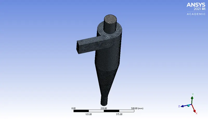
3. After the meshing is done now we open fluent for setting up the simulation
Setup Details:
1) Steady state analysis
2) Gravity in Y direction = -9.81 m/s^2
3) Viscous model: RNG k-e model with swirl dominated flow condition and enhanced wall treatment. (RNG is always used for swirling flows)
4) Discrete phase model: Interaction with bulk fluid: On
Updating of fluid volume: every 5 iterations
End tracking of particle after 50000 iterations.
Step Length factor = 0.5
5) Injections:
a) Injection: large
Injection type: Surface, from inlet
Material: Anthracite
X velocity: -3 m/s
Particle Diameter: 1e-5 m = 10µm
Particle mass flow rate = 1e-20 Kg/s b) Injection: small
Injection type: Surface, from inlet
Material: Anthracite
4. As the injection model is set now te boundary conditions has to be given
BOUNDARY CONDITION
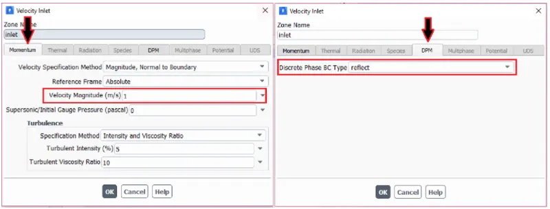
Inlet and wall:- Reflect
Outlet(Top):- Escape
Outlet(Bottom/dustbin) - Trap
SOLUTION METHOD
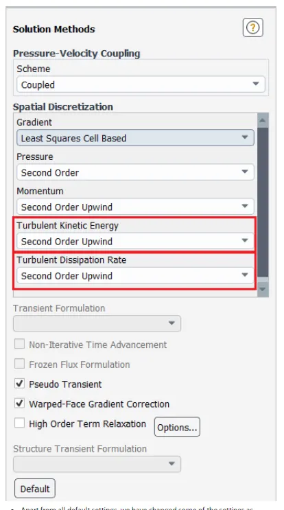
5.After setting up the boundary condition and injection model now we have to intialize the solution. Here we use standar initialization and then proceed with solving the model with 600 iterations
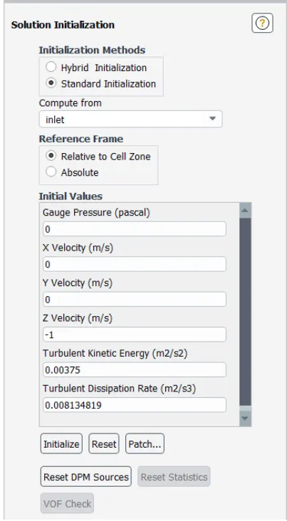
RESULTS
CASE I:5E-06 PARTICLES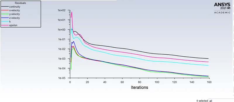
RESIDUALS
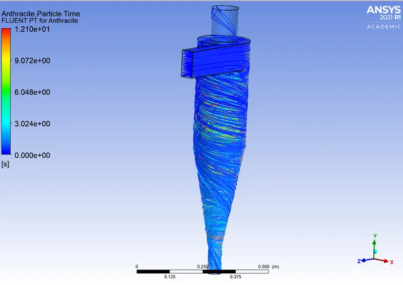
PARTICLE TIME

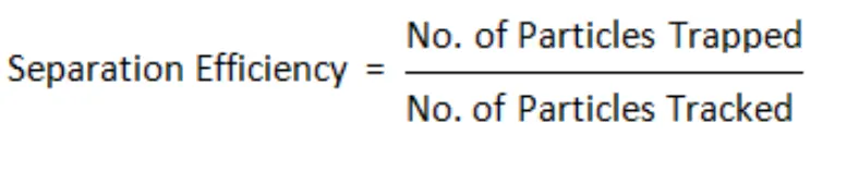
`S.E=52/124*100=41.935`
CASE II:4E-06 PRTICLES
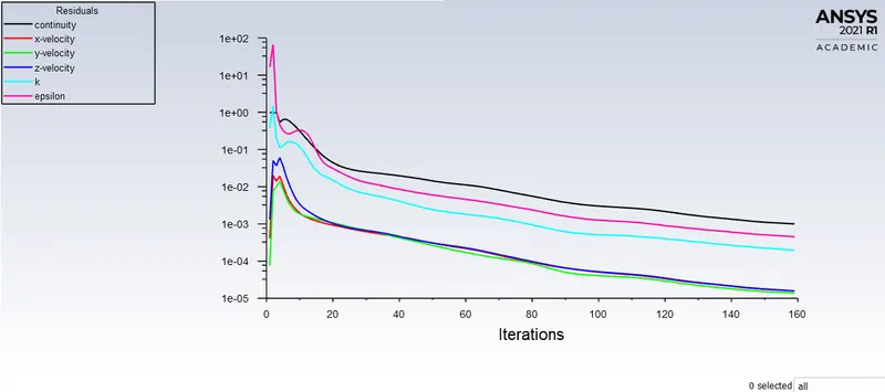
RESIDUALS
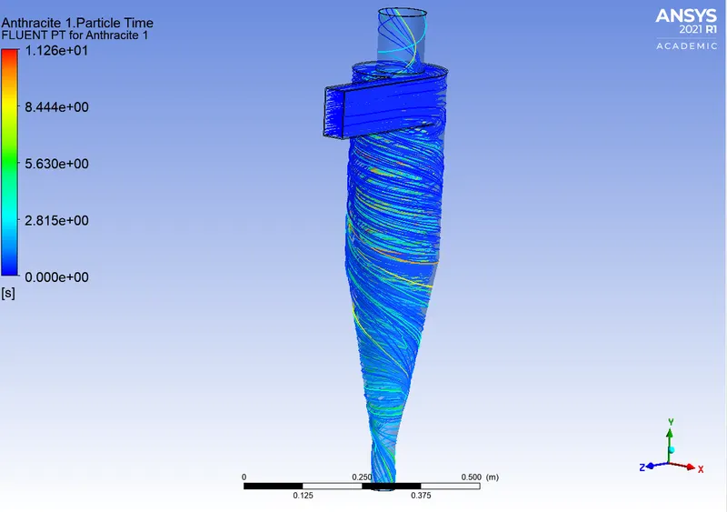
PARTICLE TIME

`SE-47/124*100=37.9%`
CASE III: 3E -06 PARTICLES
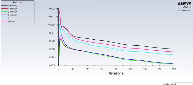
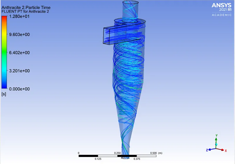
PARTICLE TIME

`S.E=36/124*100=29.03%`
CASE IV:2E-06 PARTICLES
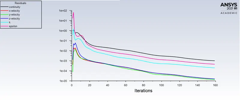
RESIDUALS
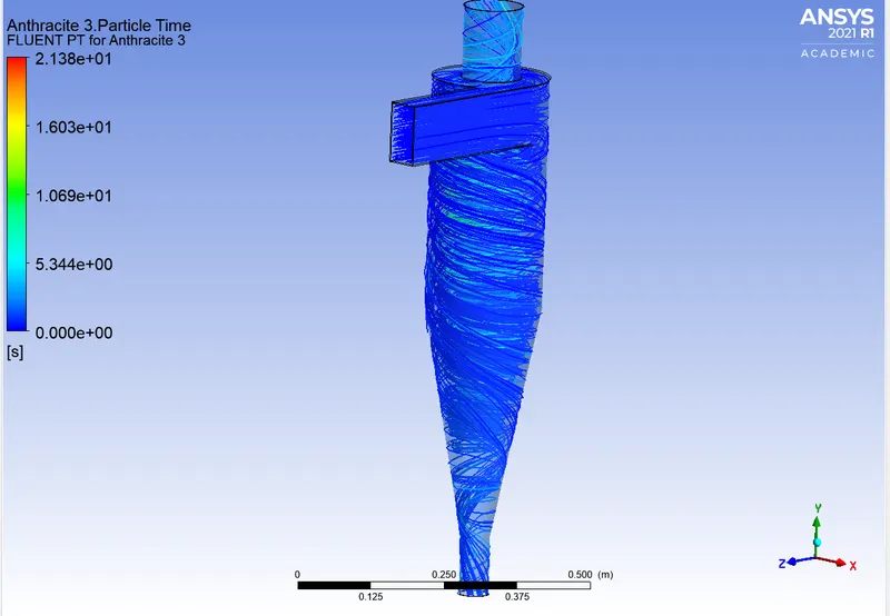
PARTICLE TIME

`S.E=30/124*100=24.19%`
CASE V:1E-06 PARTICLES
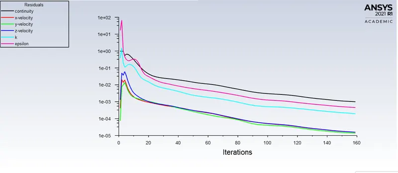
RESIDUALS
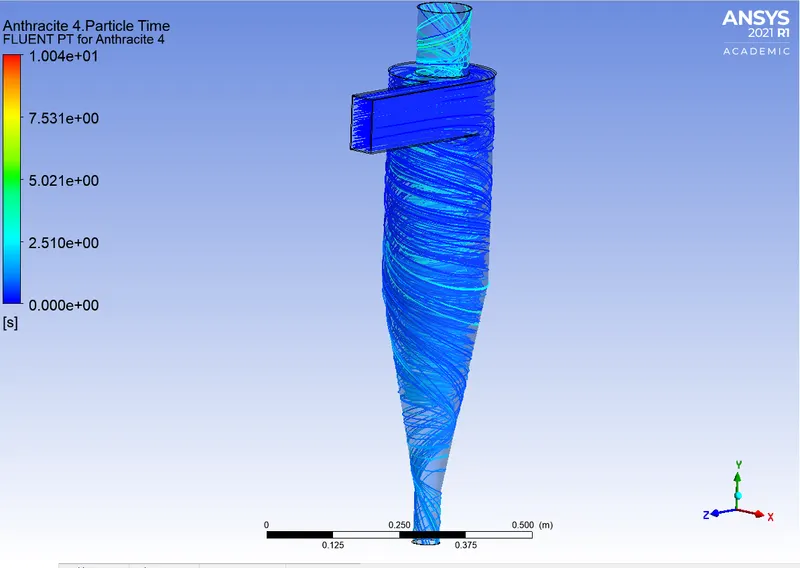

`S.E=30/124*100=24.19%`
PART II
v=1m/s
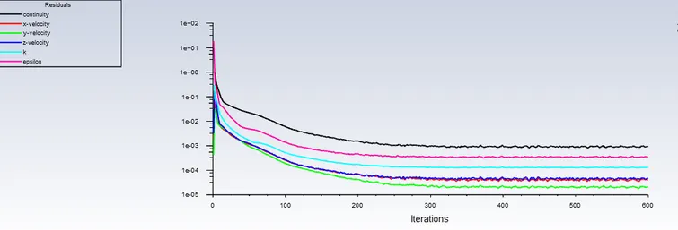
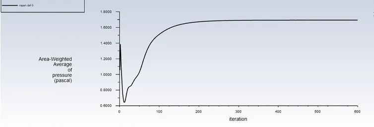
PRESSURE AT INLET
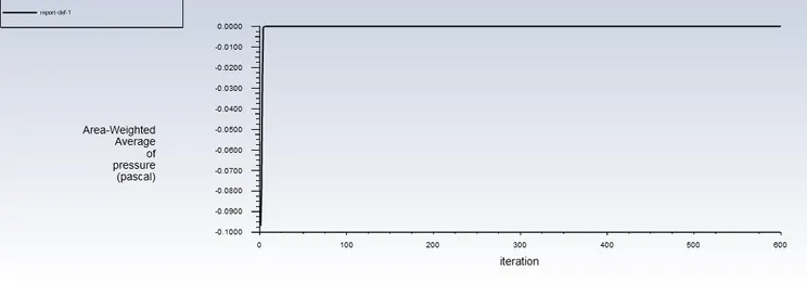
PRESSURE AT OUTLET
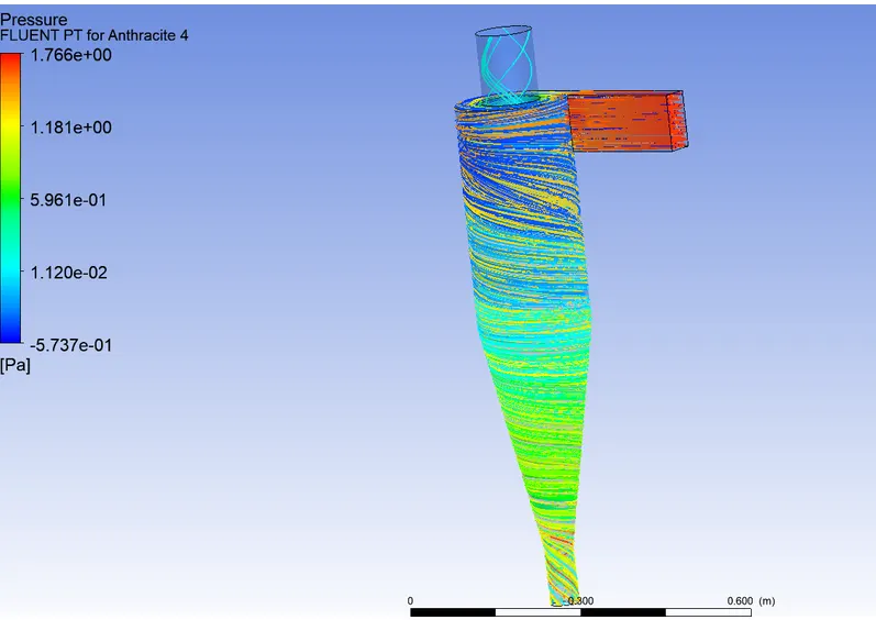
PRESSURE CONTOUR
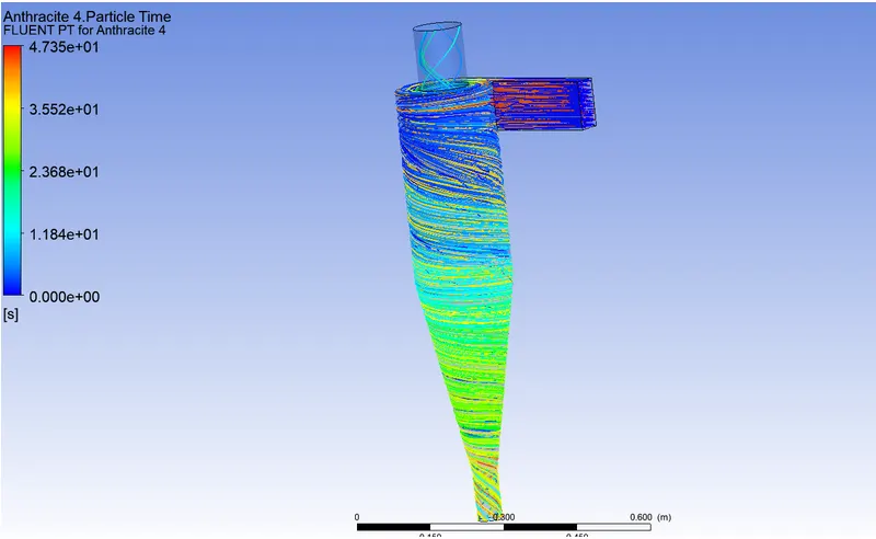
PARTICLE TIME
`SEPARATION-EFFICENCY=(11/124)*100=8.8%`
`PRESSURE DROP=INLET-OUTLET=1.629-(0)=1.629`
CASE II: V= 2m/s
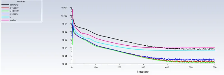
RESIDUALS
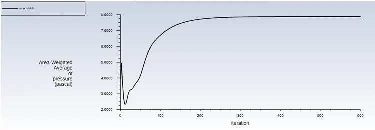
PRESSURE AT INLET
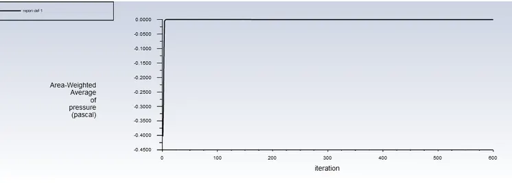
PRESSURE AT OUTLET
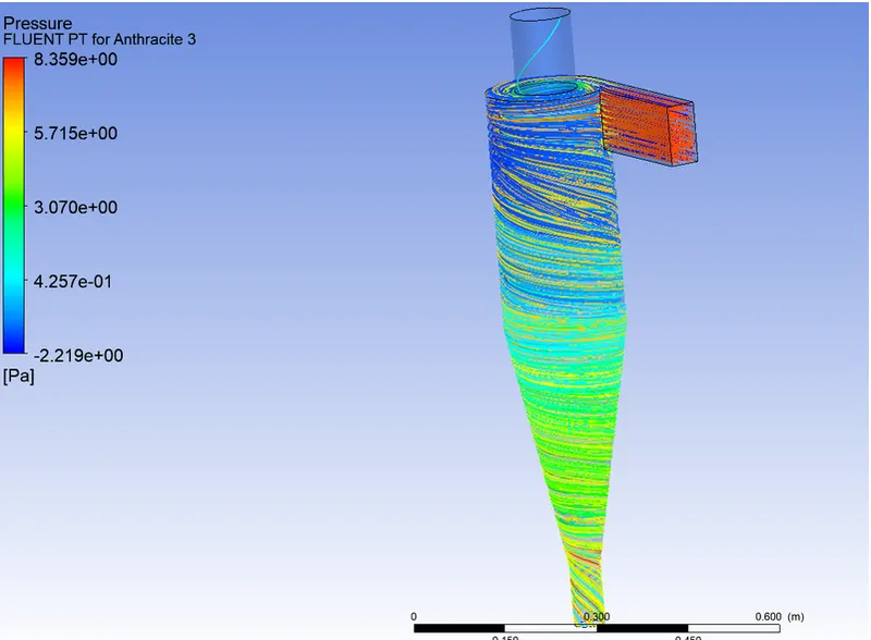
PRESSURE CONTOUR
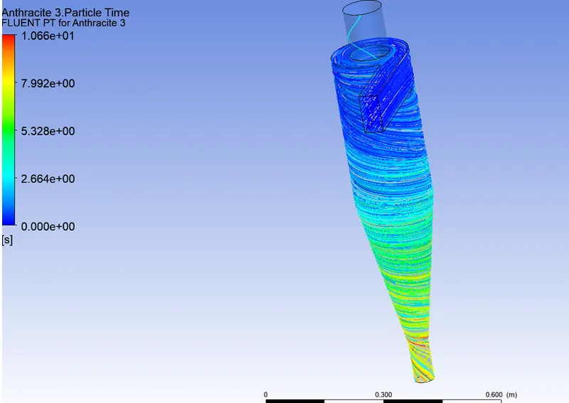
PARTICLE TIME
`SEPERATION-EFFICIENCY=(32/124)*100=25.86%`
`PRESSURE DROP=INLET-OUTET=7.87-(-0.000621)=7.87`
CASE III: V=3m/s
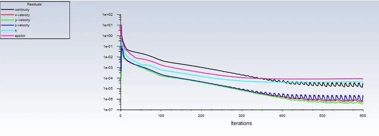
RESIDUALS
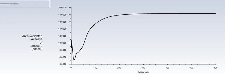
INLET PRESSURE
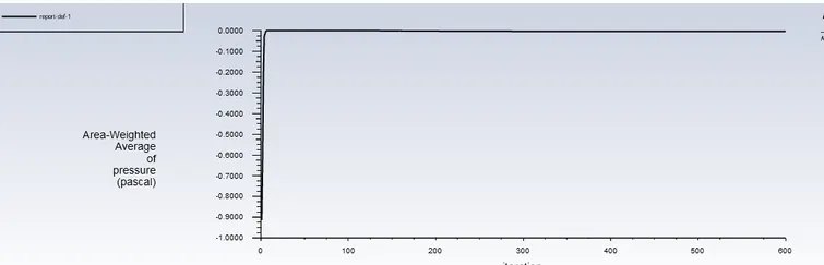
OUTLET PRESSURE
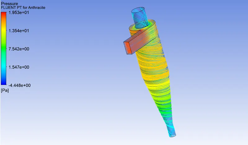
PRESSURE
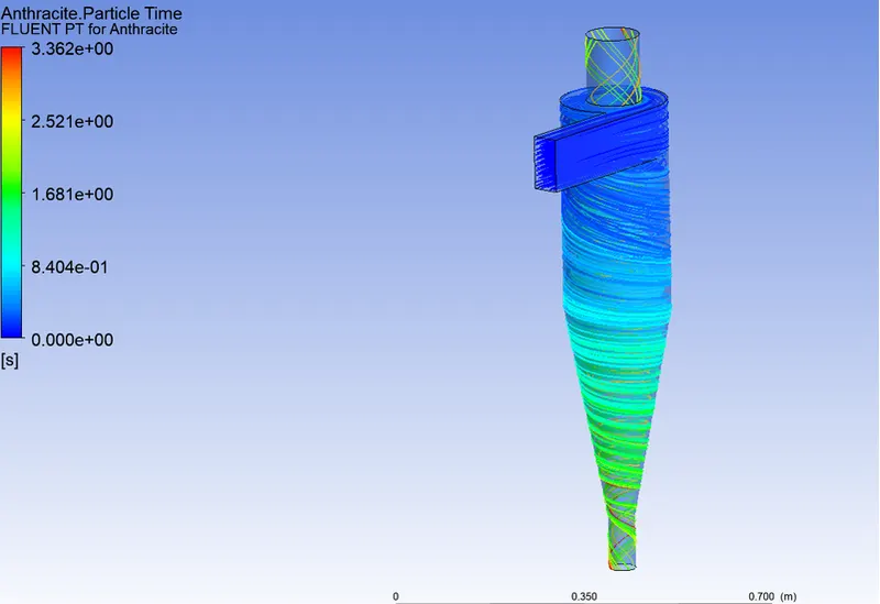
PARTICLE TIME
`SEPARATION -EFFICIENCY=(124/124) *100=100%`
`PRESSURE DROP =INLET -OUTLET=18.3191-(-0.00365)=18.32275`
CASE 4: V=4m/s
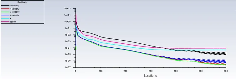
RESIDUALS
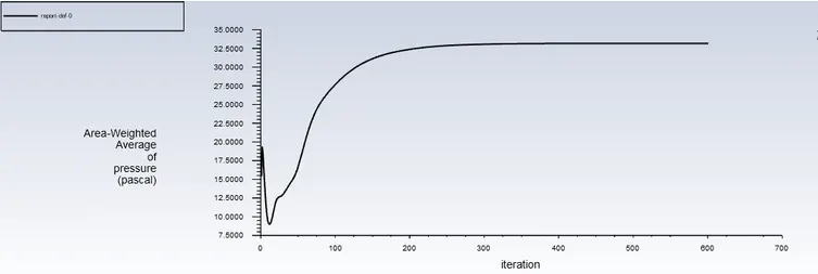
INLET PRESSURE
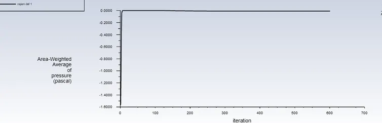
OUTLET PRESSURE
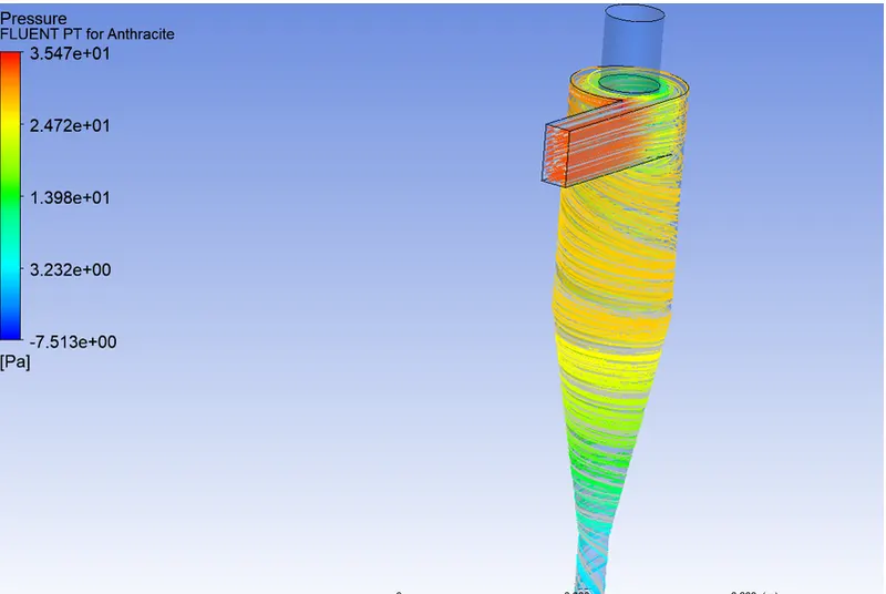
PRESSURE CONTOUR
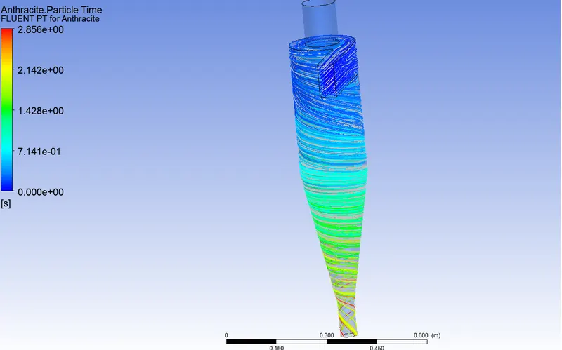
PARTICLE TIME CONTOUR
`SEPARATION -EFFICIENCY=(124/124)*100=100%`
`PRESSURE DROP=INLET-OUTLET=33.17-(-0.0081)=33.178`
CASE V- V= 5m/s
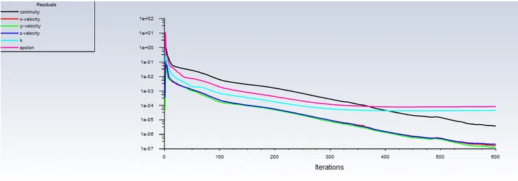
RESIDUALS
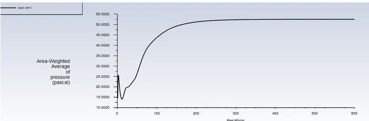
INLET PRESSURE
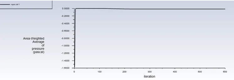
OUTLET PRESSURE
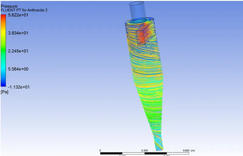
PRESSURE CONTOUR
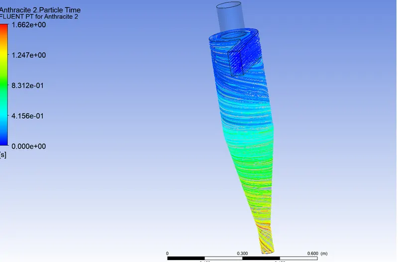
PARTICLE TIME
`SEPARATION -EFFICIENCY= (124/124) * 100=1`
`PRESSURE -DROP=INLET-OUTLET=52.49-(0.01432)=52.5pa`
CONCLUSION:
• From the observations of Part_l & Part_2 cases, we can conclude that Separation efficiency of Cyclone Separator depends on both Diameter of the Particles and also on the Velocity of the Particles.
• Also we can conclude that in cases of Part_2, there are more efficient results. So the Velocity is more effective variable for higher efficiency.
• Efficiency of a Cyclone Separator has direct effect on the Pressure Drop. • Higher efficiency Cyclones has highest Pressure Drops. •
Higher the Velocity, the higher the Pressure Drop and the highest the Efficiency.
• With increase in Diameter of Particle and Velocity of Particle, Particle Resident Time decreases.