Machining with Planer Challenge Using ANSYS Workbench
AIM:
To perform an explicit dynamics simulation to find out the Equivalent Stress, Total Deformation and also insert a User-defined result to calculate the temperature of the body. You need to perform this for 2 cases. Case one will be with a cutting velocity of 20000mm/s and case two will be with a cutting velocity of 15000mm/s.
THEORY:
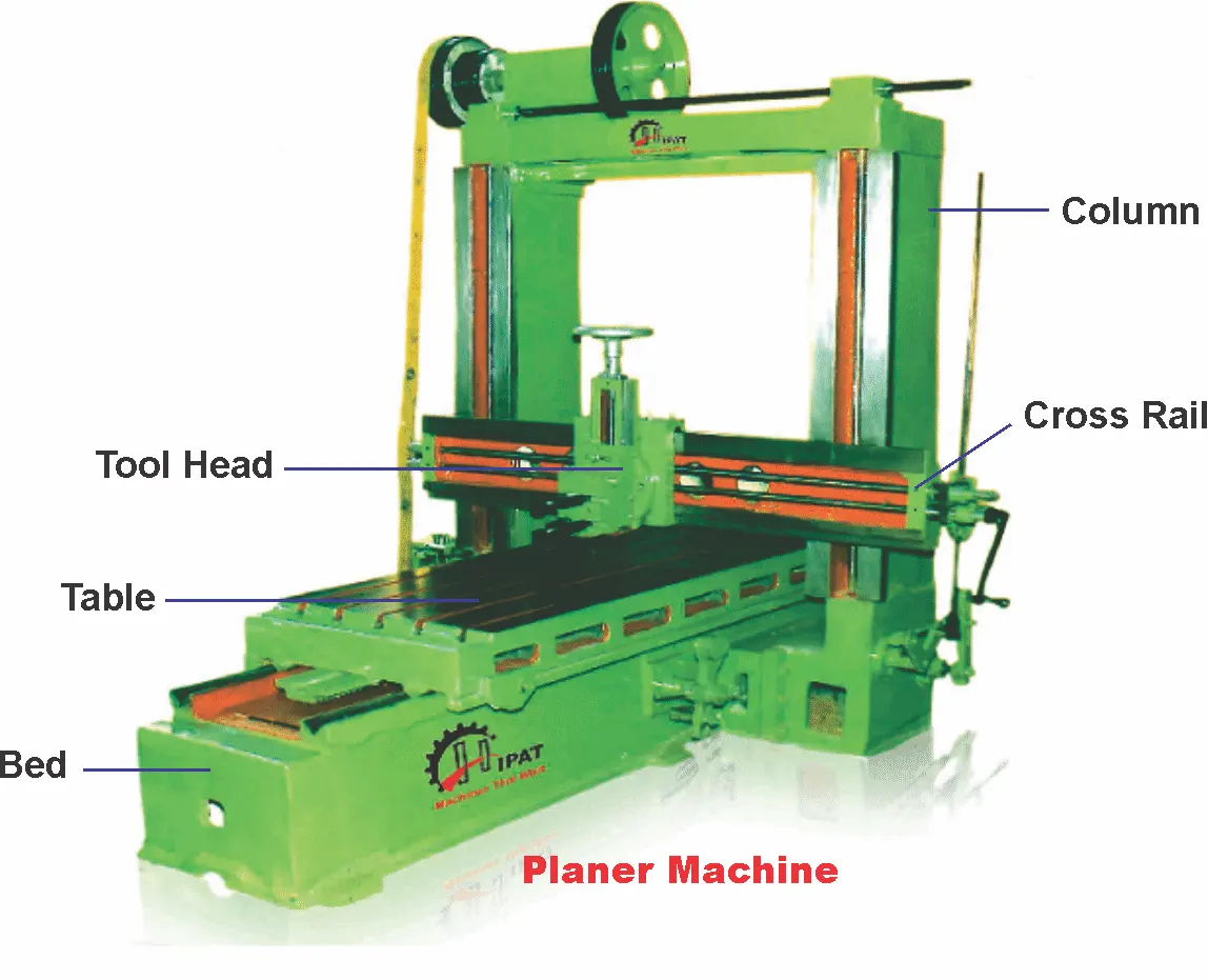
The principle of the planner machine is the concept of relative tool-work motions. Reciprocation of the tool or job and the slow, intermittent transverse feed motions are imparted to the job or tool by the fast straight path cutting motion.
All the operations done in planning machines can be done in the shaping machine. Stroke length, larger size, and higher rigidity enable the planning machines to do more heavy-duty work on large jobs and their long surfaces. It produces planes and flat surfaces with a single-point cutting tool. A planer machine is large and massive as compared to a shaper machine. The planer can do machining heavy workpiece, which cannot be done on a shaper surface.
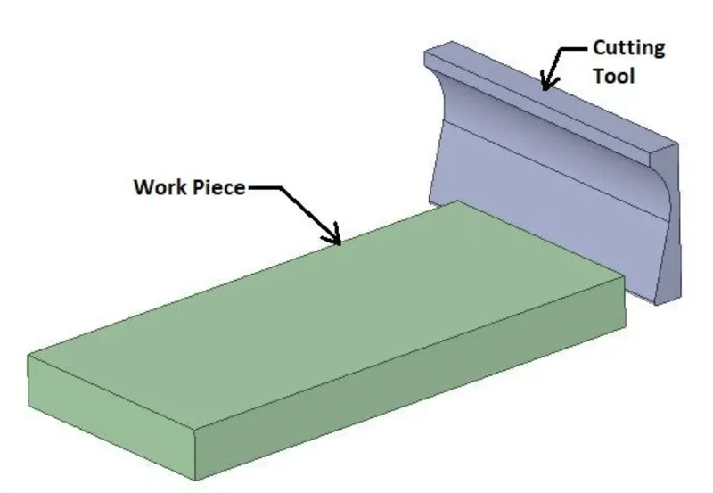
GEOMETRY
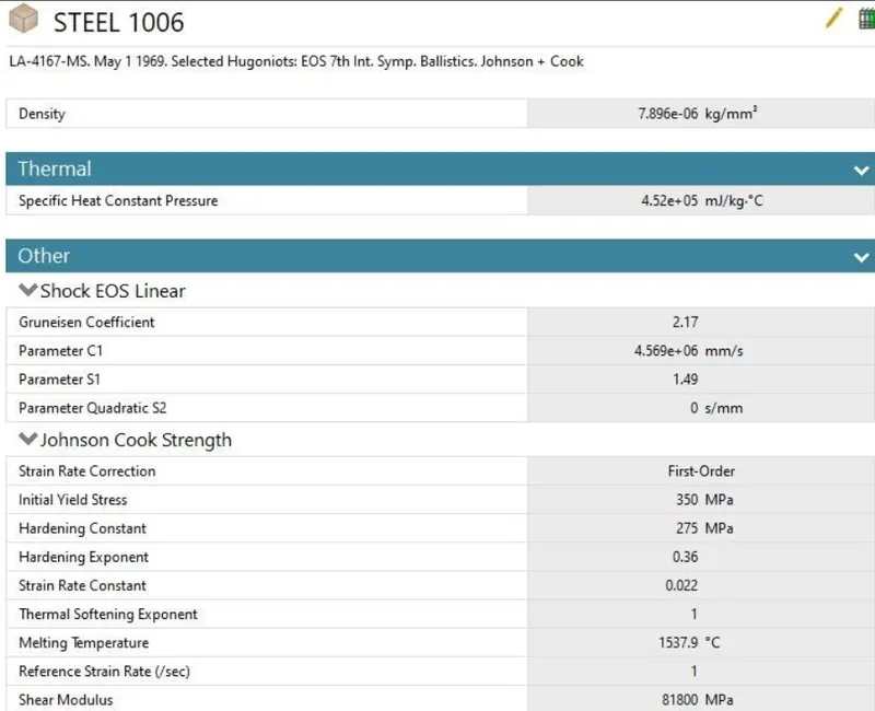
MATERIAL USED:
PROCEDURE:
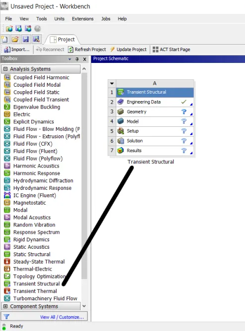
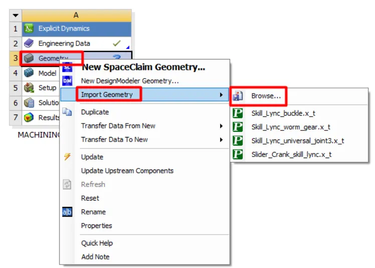
1:We import the explicit dynamics module into the Ansys workbench and this can be done by simple drag and drop and it can be renamed for our convenience
2:Part model and material The model was used as given and the material for the workpiece was taken as steel 1006.Now we import the model and check-in SpaceClaim to verify if any abnormalities occur
3.Since the focus of the analysis is only on the workpiece, the cutting tool was defined as rigid. This can be chaged in stiffness behaviour in mechanical module
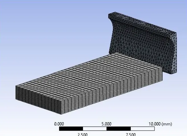
4:The part was meshed using ANSYS Mechanical module. The cutting tool was meshed with tetrahedron elements using patch conforming method and the workpiece was meshed such that each of the smaller edges has 10 divisions.
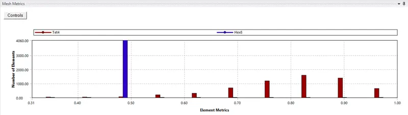
MESH METRICS
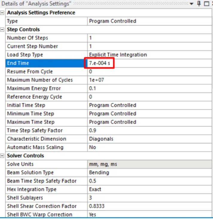
5: Analysis settings The analysis is carried out in a single step, with the end time step = 7.5e-4, maximum energy error as 0.1 and all other settings were kept default
6. The bottom face of the workpiece was given fixed condition and the tool was given a velocity of 20000mm/s and 15000mm/s in the X direction.
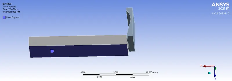
7. List the required outputs from the solution panel and we run the simulation using the solve button
RESULTS:
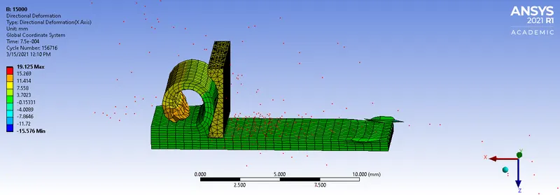
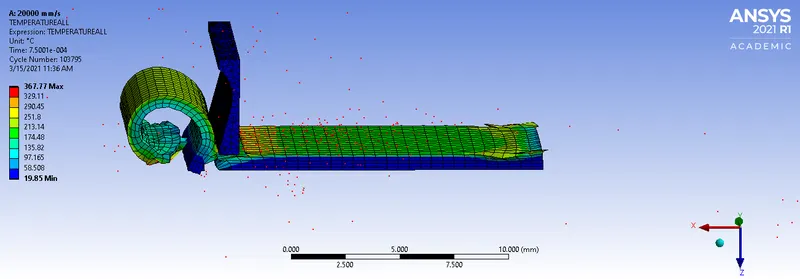
Results Case 1: Velocity = 20000mm/s Case 2: Velocity = 15000mm/s
DIRECTIONAL DEFORMATION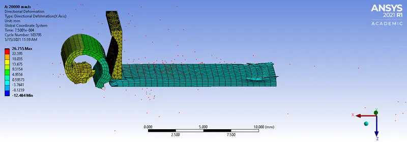
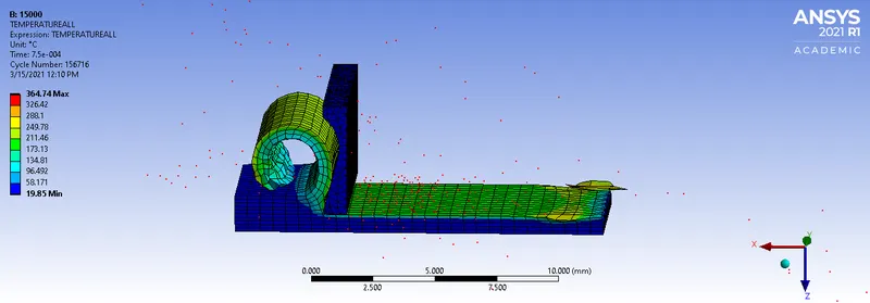
TEMPERATURE
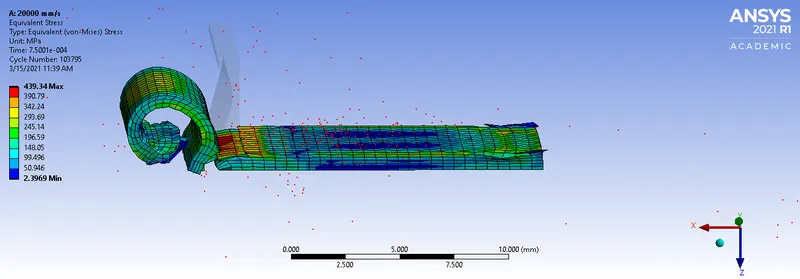
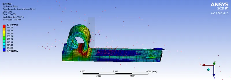
VON-MISES STRESS
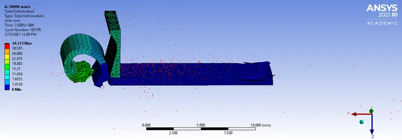
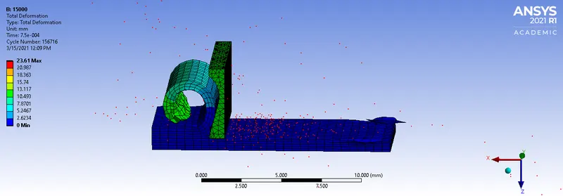
TOTAL DEFORMATION:
CONCLUSION:

The maximum value for the deformation and temperature developed is in case 1, while the maximum stress is developed in case 2. The relation between cutting force and cutting velocity is such that, it decreases with increasing velocity. Due to the lower force, the stress developed is also lower in case 1. The total deformation is larger in case 1 because the velocity is higher in this case, hence the tool travels a longer distance in the same given time. Due to this long travel, the machined surface is also large. This results in a higher temperature being developed in case 1.