Editing the engine data file and 3D mesh the rest of the components
AIM:
To obtain the speed of the sound and 3D mesh the given component
THEORY:
Tetrahedral is a four- nodded solid element that can be generated through the tria element by creating a volume and also through the existing volume of the geometry. These elements are used where the geometry has high thickness and complexity.
PROCEDURE:
1.To calculate the speed of sound
Speed of Sound=`root`E/R`
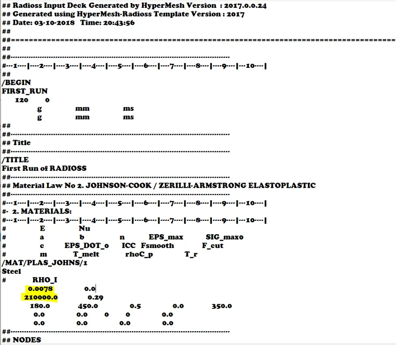
E=210000 g/(mm) (ms)
RHO=0.0078 `g/(mm)^3`
Speed of sound=5188.74 mm/ms
==============
2.Length of rail=1000mm
Time taken for the shock wave to travel =Length/Speed=1000/5188.74=0.192m/s
==============
3.Time for sound to travel the length of rail=0.192m/s
==============
4.Editing the engine file
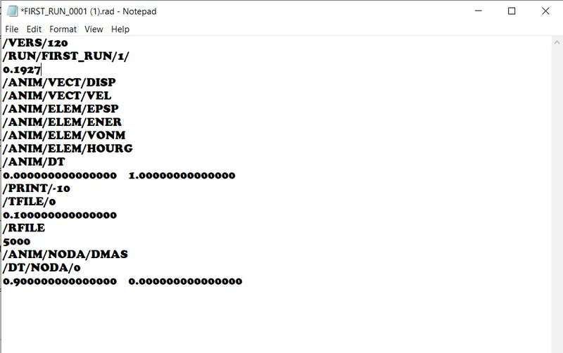
The stress wave can be monitored, moving from one end of the rail to the other during impact by changing the time equal to our calculated time 0.1927
============
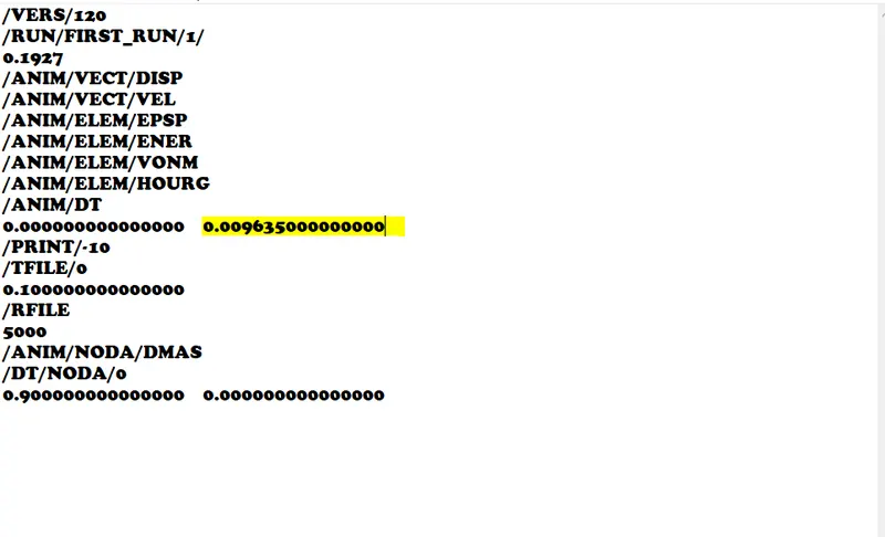
To set the frequency of animation output to a time that will give 20 animation steps(/ANIM/DT) we just have to change the value below (/ANIM/DT)
In order to get 20 animation steps, change this value to 0.1927/20=0.009635
===========
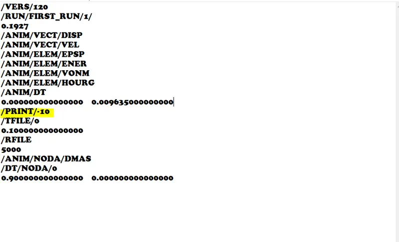
6. Change /print -10.
The print value has been set to -10
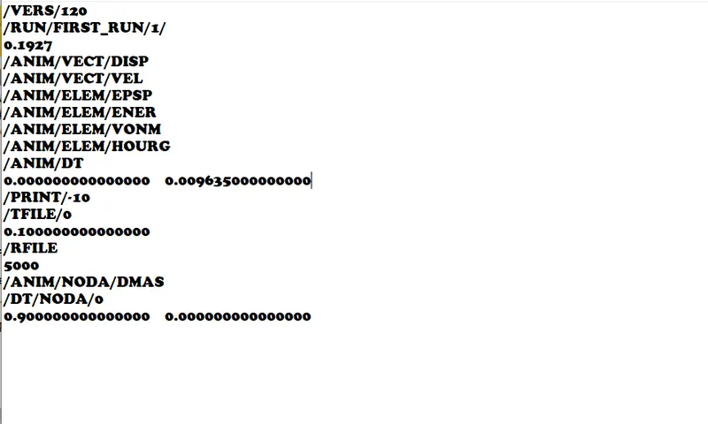
Final Engine File
===========
TETRA MESHING
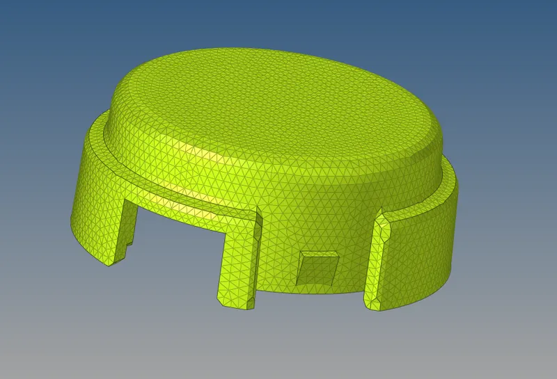
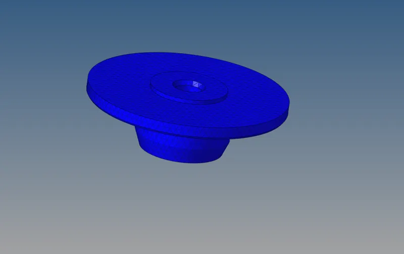
Import the given component in hypermesh
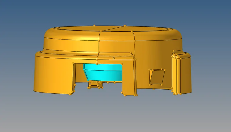
2D mesh is created using 2D-->Automesh-->Trias
Here we use trai elements as the mesh type and element size is 5mm and mesh is done
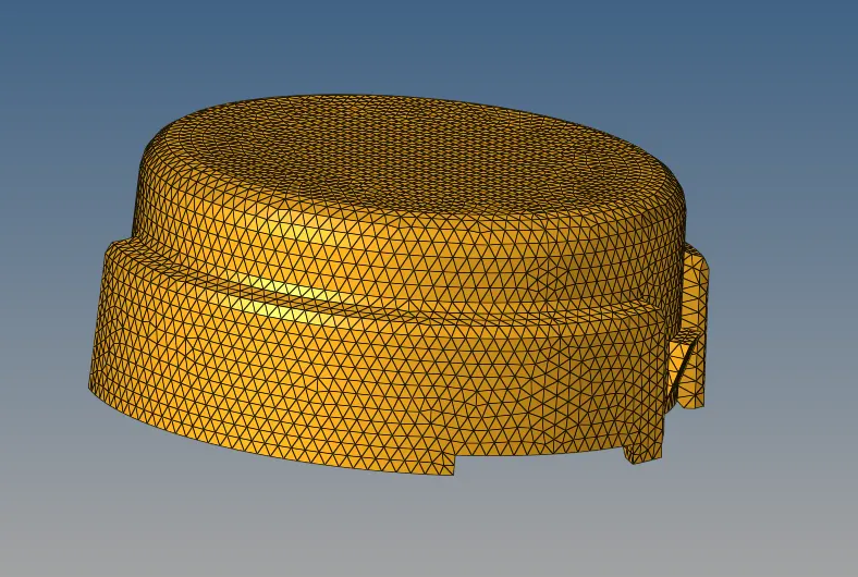
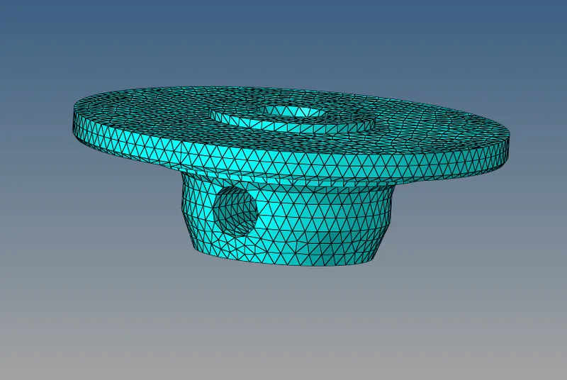
Now the model is ready to perform the Tetra Meshing. Select the 3D→ tetramesh option.
In the tetra mesh panel, select the elements under the “Fixed trias/quads to tetra mesh” option
After selecting the elements, click on the “Mesh” button
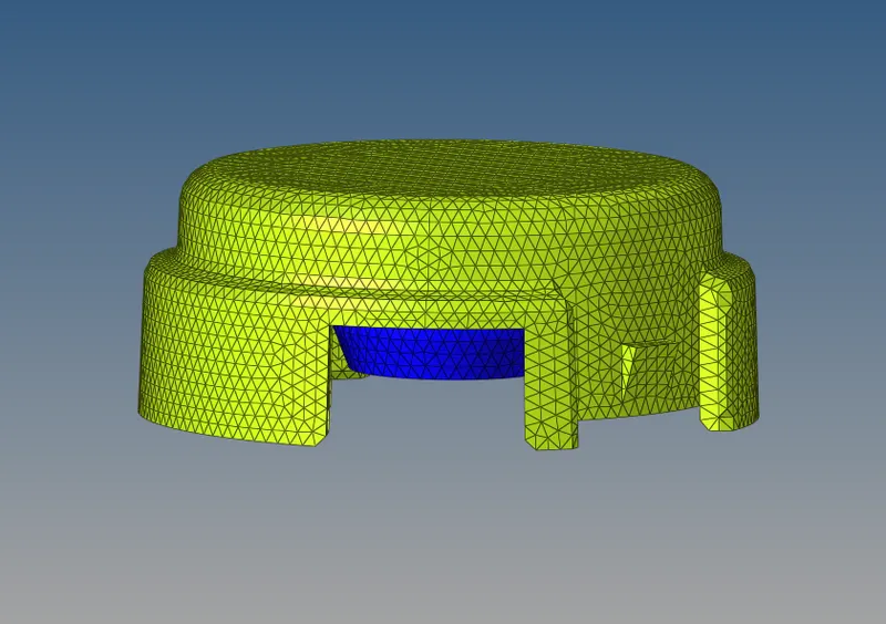
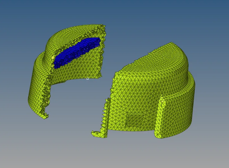
Elements masked to view the tetra elements
As we get 0 elements failing for tet collapse we can ensure the mesh quality and accept the mesh
HEXA MESHING:
Import the given component in hypermesh
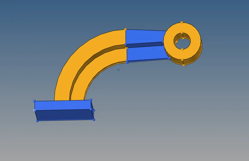
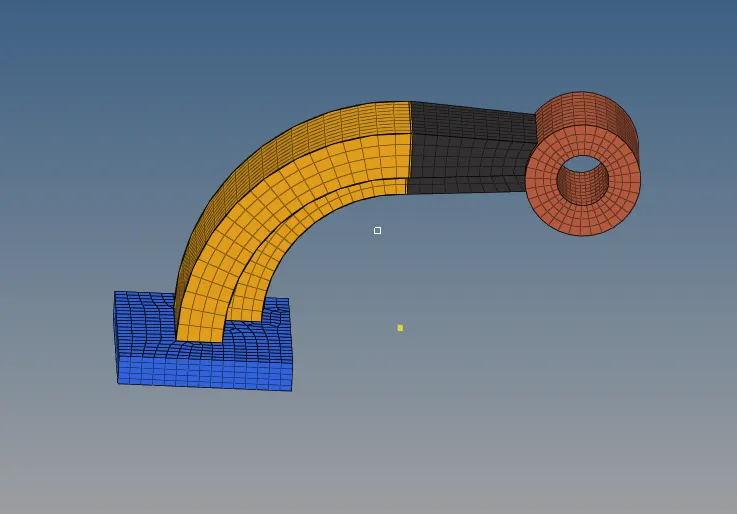
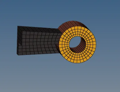
We check for any surface defects using the topo mode.Here we have 4 components i.e base,arm straight,arm curve and boss.
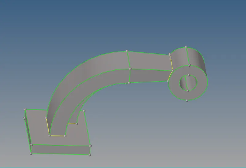
We move on to the meshing part by part. As we need hexa meshing here we set the shell mesh using quads only
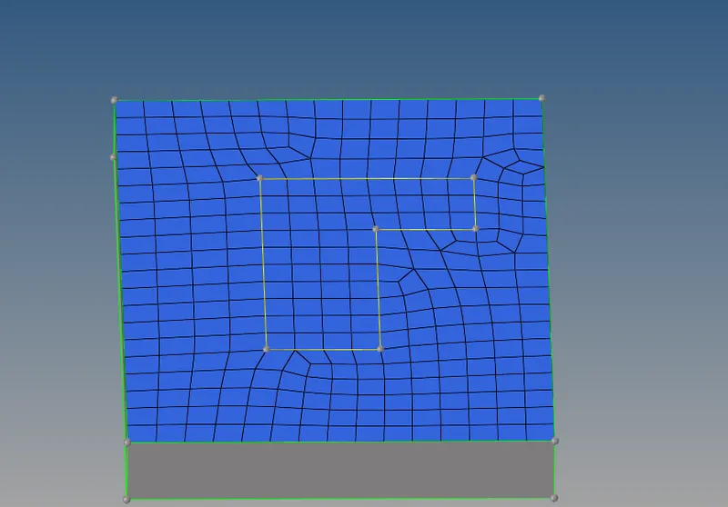
We then use the 3D-->elem offset option to create the Hexa mesh of the quad elements. Select the above elements and then set the number of layers=5 and total thickness=25 and click offset+
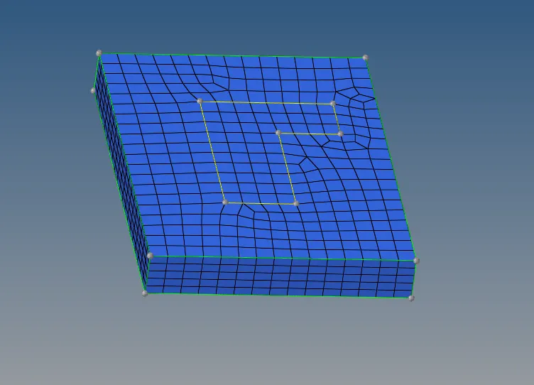
Since net we have a curved geometry we can use the 3D-->spin option-->spin elem option. Here we select the base elements and spin it according to the base node and axis
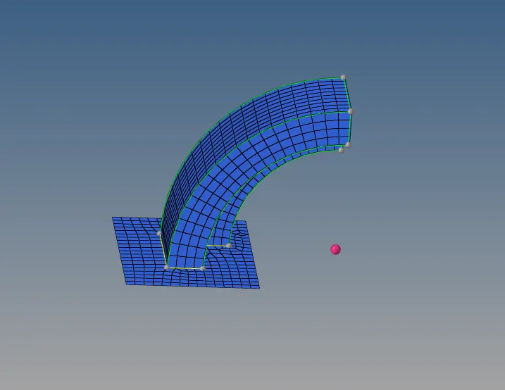
Next part we use linear solid as we have the same area to mesh with decreasing cross-section. Hence we mesh the other part to wich the mesh should be extended
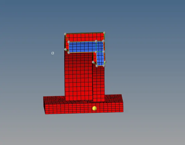
Then we select the required elements and specify their respective alignment and click on solids options. We should ensure the mesh on both faces should be the same in number

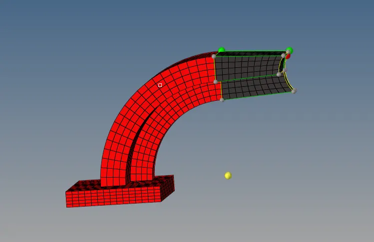
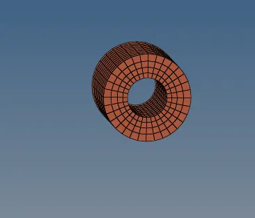
Now we have our last compnent boss to be meshed.Here we follow the solid map meshing techinque. Here we first mesh the top circular surface and drag it among a surface line along the dimesnsion to generate the hexa mesh
RESULTS:
The components were meshed according to the criteria and the required quality criteria were maintained