Structural Meshing of IP Substrate
AIM:
To mesh the given model of IP SUBSTRATE within the given quality criteria
|
S.No |
Quality Criteria |
Value |
|
1 |
Target/Average length |
4 |
|
2 |
Minimum Length |
2 |
|
3 |
Maximum Length |
6 |
|
4 |
Aspect |
3 |
|
5 |
Warpage |
15 |
|
6 |
Skewness |
45 |
|
7 |
Jacobian |
0.7 |
|
8 |
Minimum Quad Angle |
45 |
|
9 |
Maximum Quad Angle |
135 |
|
10 |
Minimum Tria Angle |
30 |
|
11 |
Maximum Tria Angle |
120 |
|
10 |
Tria Percentage |
15 |
INTRODUCTION:
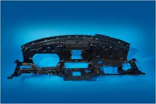
IP(Instrument Panel) Substrate is the longest and thinnest plastic composite part present in a car. They are usually made of plastic injection molding i.e Injection molding is a manufacturing process for producing parts by injecting molten material into a mould, or mold. Injection molding can be performed with a host of materials mainly including metals, glasses, elastomers, confections, and most commonly thermoplastic and thermosetting polymers.
Instrument panels are generally made of acrylonitrile-butadiene-styrene(ABS) or poly carbonate alloys,polycarbonates, modified polyphenylene ether, or SMA resins. These plastics allows for complex designs
They are designed to house air vents,cup holders , glove box, steering,tachometer,air bags, entertainment system etc. The panel is robust and light. The substrate is the base material that runs through IP or occupies the most region
THEORY:
Computer-aided engineering also known as CAE is the broad usage of computer software to aid in engineering analysis tasks. It includes finite element analysis, computational fluid dynamics, multibody dynamics, durability, and optimization
Meshing is the foundation for all FE based CAE activity. A quality mesh is a prerequisite for reliable CFD and FE analysis projects as is a thorough comprehension of the effects of a mesh on a result. A geometric cleanup helps us to perform meshing efficiently and keep the mesh within the quality criteria
We need to take a lot of care for these element quality as these criteria will make us understand how much the elements are deviated from the ideal element. Since they represent the geometry during a simulation, poor elements will misrepresent the geometry and will lead to inappropriate results.
These are the important quality parameters we should take care
Minimum and Maximum length:
It is the minimum or the maximum length we are maintaining in the mesh generated and should enusure no element goes below or above this criteria
Aspect Ratio:
The aspect ratio is the ratio of Maximum length to the Minimum length.
In simple terms, when you see a quad element one side smaller than the remaining three sides then you will have your element failed for aspect ratio. Being said this,the shape of a perfect quad element has all the sides equal so the ideal value of the Aspect ratio is one.
Due to geometrical constraints not every time, you can achieve a perfect quad and this is exactly why you will be given a tolerance value. This tolerance value depends upon the accuracy required. Having a large aspect ratio will reduce the accuracy of your result.
Skewness:
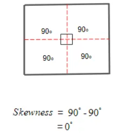
Skewness is the quality of the elements in terms of angles. For a Quad element,
Skewness=`90 -theta`
In case of an ideal quad.
Warpage:
Whenever you have a quad element in two different planes then you will have your element failing for Warpage. Ideally, your element should be in a single plane, when they are in two different planes if you split the quad along the diagonal and measure the angle between the normals it will give your element Warp angle. Warp angle is the angle of plane deviation in your element which is also known as Warpage.
When you have your element failing for warpage then the results of the simulation are going to be inaccurate. Features like fillets are more prone to have a warped element as the geometry itself will be in two different planes. Considering all these geometrical constraints and accuracy we can have a tolerance for this criteria.
Jacobian:
Every element will have its own coordinate system which is known as the Natural Coordinate system. From this coordinate system it is difficult to derive a direct solution thus these elements' natural system has to be converted to a global system.
So in order to map the elements from its natural system to the global system, these elements have to be in ideal shape.
As we know, not all the time we can have an ideal shaped element in the geometry so tolerance is established. This deviation of the element from the ideal shape is measured through Jacobian. The Ideal value of Jacobian is 1.
Chordal Deviation:
This chordal deviation is the measure of how well the elements captured the curves. When you have a small fillet and if your element size is bigger than the size of the fillet then you can expect this chordal deviation error. You can mesh with a smaller element to capture the fillet or you can increase the tolerance value of chordal deviation considering the accuracy required.
TOOLS USED:
Delete: The universal delete function can be used to delete unwanted entities like curves, faces etc
Release: This option helps to release triple cons etc to make it proper
Fill hole: This function fills holes in the faces to fill gaps
Coons-Project: Create curves and project to the surface which is used to patch up the surfaces
Paste: This function is used to paste nodes
Split: This function splits the quadrilateral and triangular shell element into smaller ones
Reconstruct: This tool helps to create a better quality mesh in regions used
Project: This function projects coons or 3d curves onto the faces
Swap: This function helps to swap the shell element to the required destination
Cut: This function helps to cut faces or make splits to bring out uniform mesh in the model
Extend: This tool helps to join required faces to another face
Offset: This function helps to take mid-surface of the components
Middle: This tool helps to take mid surface in between of two components
PROCEDURE:
Import the given IP substrate model onto ANSA
- Geometric cleanup
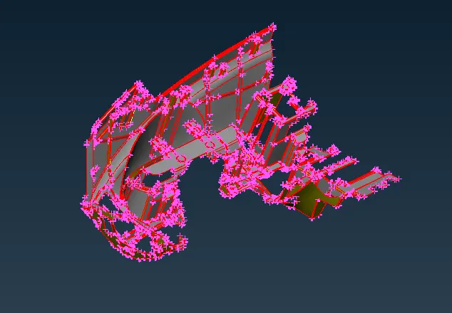
First of all we have to perform Topo on the given model to stitch the surfaces together using the Faces->Topo option
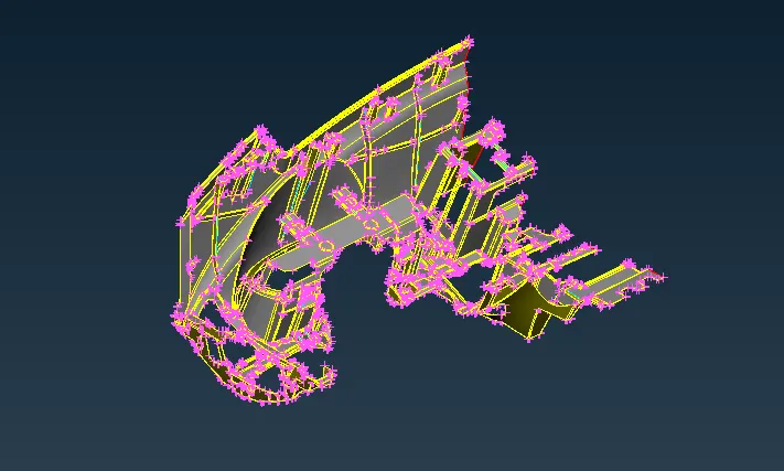
We then have to orient the surfaces properly using Faces->Orient Option
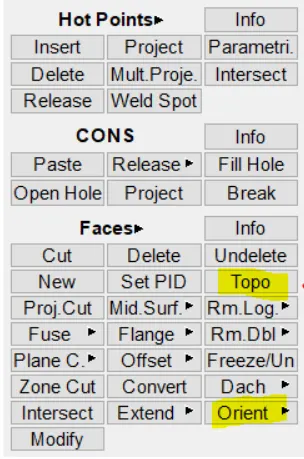
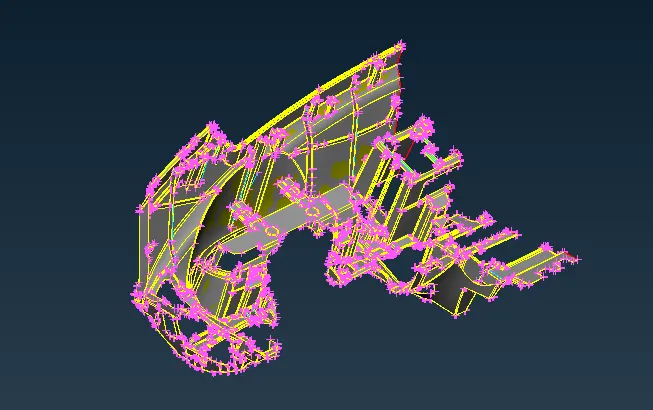
The model is checked for any geometrical errors using the Check geometry option 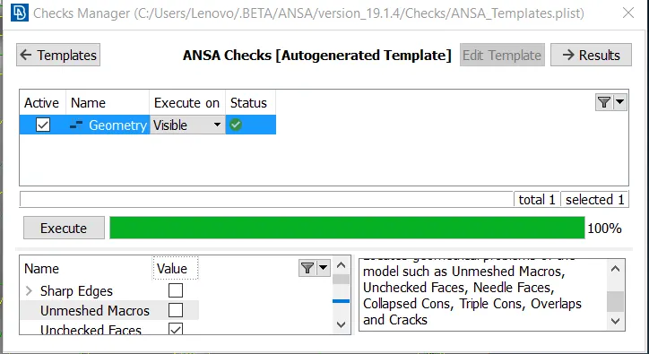
- Midsurface Extraction
The model is ready for extracting the mid-surface
ANSA will not be able to handle auto-mid for such complex surfaces hence we go for manual mid surfacing. Here the component is of uniform thickness of 0.6mm thickness.
We use the Faces->offset command and we can select the faces of uniform thickness at once using the feature option and specifying the default feature angle as 40.
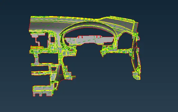
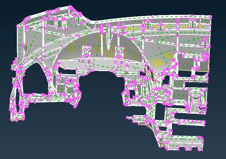
IP substrate model The faces offset option
For the ribs in the component can be extracted using Faces->Midddle->Multi/Single as shown below. Then select the faces and accept the faces. We then use the Faces->Extend option to extend the ribs to the surfaces
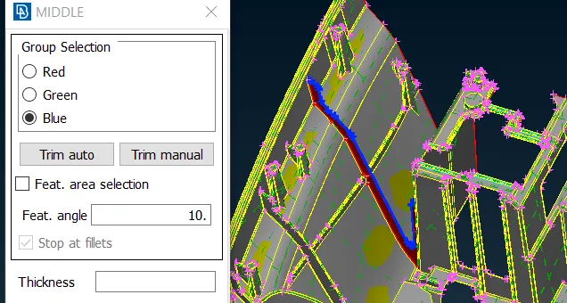
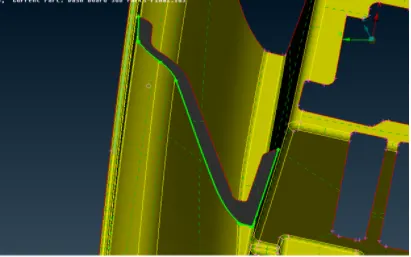
Selecting the required faces for middle->multi option Selecting the side of the mid surface to extend
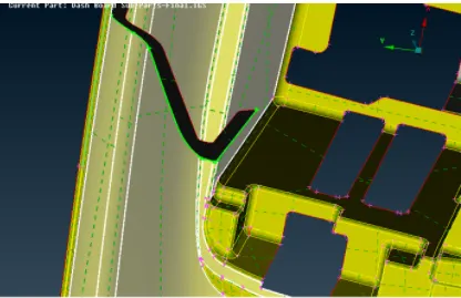
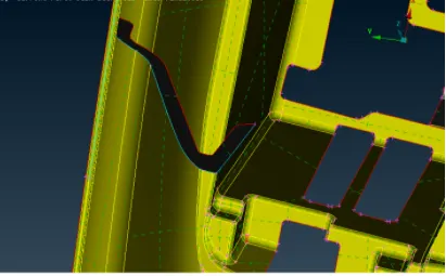
Selecting the faces to which the mid surface The extended mid surface
should be extended
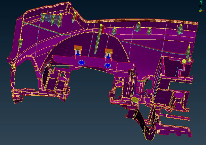
Similarly, all the surfaces can be extracted individually and we get a mid-surface for the component
- Meshing
The next step after mid surfacing is 2d meshing. Prior to this, we have to setup the 2d mesh parameters and the quality criteria in their respective tab
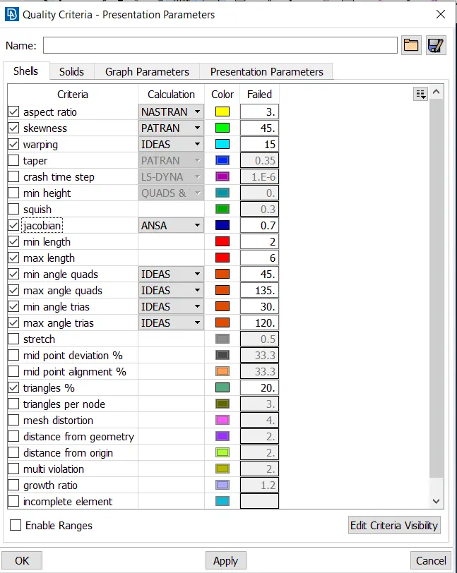
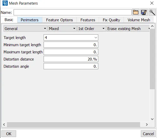
The given model is meshed according to the quality criteria using the Mesh Generation->Spot Mesh option
After meshing draw shell as solid option is turned on and the mesh can be seen with the thickness enabled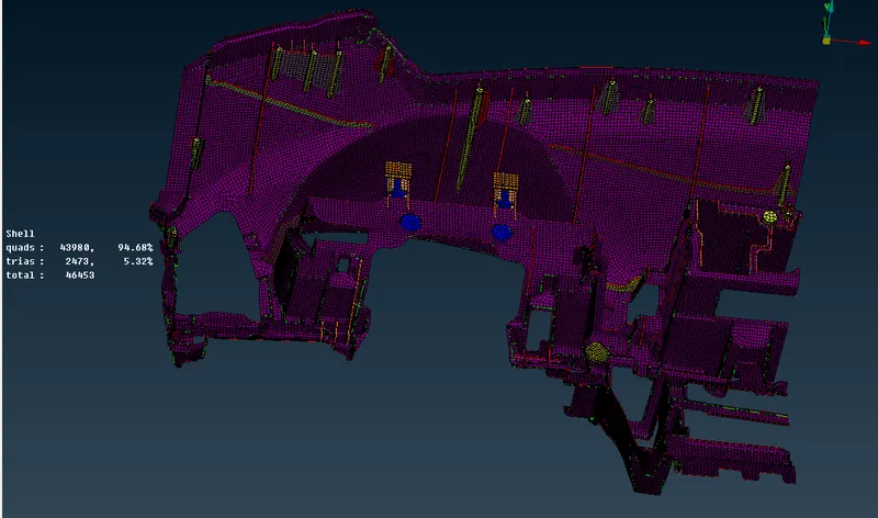
RESULTS:
Extracted Mid-surface
Meshed model
LEARNING OUTCOMES:
Learned to mesh complex models having many intricate parts and features with different thickness
To capture the features more accurately