Connection representation of a frame assembly using hypermesh
AIM:
To create connector and Attach the various parts of the given model
1. Right_Rail_2 & Front_truss_1:- Seam-Quad(angled+capped+L)
2. Left_Rail_2 & Front_truss_1:- Quad elements
3. Front_truss_2, Front_truss_1 & Right_Rail_1:- Spot weld with 3 Layers and 5 mm Diameter
4. Front_truss_2, Front_truss_1 & Left_Rail_1:- Hexa (Adhesive)
5. Rear_truss_2 & Right_Rail_2:- Bolt Connector
6. Rear_truss_2 & Left_Rail_2:- Bolt Connector
7. Right_Rail_1 & Right_Rail_2:- Spot-weld with Rigid Elements
8. Left_Rail_1 & Left_Rail_2:- Spot-weld with Spring Elements
9. Rest all the component left Join them with suitable connectors
PROCEDURE:
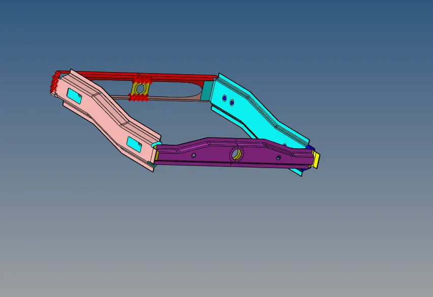
- First, we import the given model in hypermesh
- Now we mesh all the individual components with a target element length as 6mm
- Now we have to assign the required connectors as required
- After meshing we go to 2d/1d-> connectors option in that we go to seam and select the seam quad (angled+ capped + L) and select the components which we have to connect and make sure that connectors are realized.
1. Right_Rail_2 & Front_truss_1. For these connectors, spacing is given 4mm and tolerance 20mm.
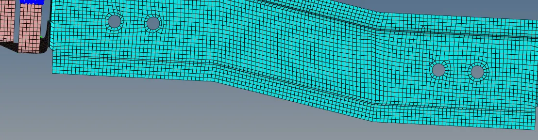
2. Left_Rail_2 & Front_truss_1: Similarly we select the quad connector and select the components to connect

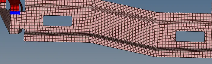
3. Front_truss_2, Front_truss_1 & Right_Rail_1:To do spot weld in frame go-to spot option in connectors and select the weld in 3 layers and 5 mm diameter
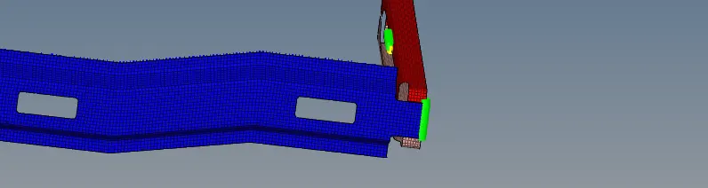
4. Front_truss_2, Front_truss_1 & Left_Rail_1: For Hexa adhesive connectors to the seam and select the hexa and select the components to connect and create the connector
5.Rear truss 2 & Right Rail 2- Bolt Connector
We go to 2d / 1d connectors and select bolt and at the desired location we add the bolt connectors with a tolerance around 15
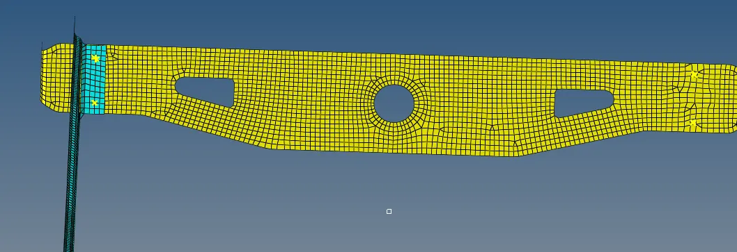
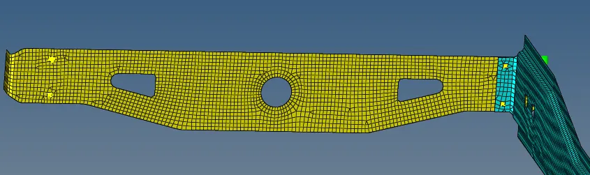
6.Rear_truss_2 & Left_Rail_2:- Bolt Connector
Here bolt connectors are placed at two positions and given a tolerance of 15
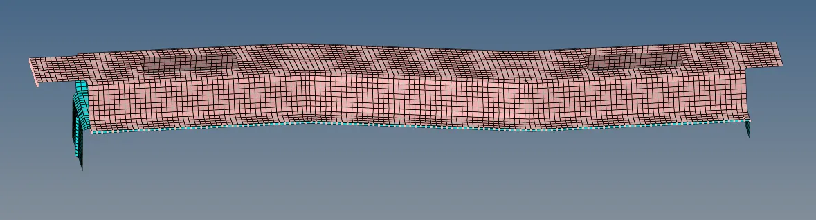
7. Right_Rail_1 & Right_Rail_2 : Spot-weld with Rigid Elements
At both, the side free edges added spot weld with rigid elements are added with a tolerance of 15
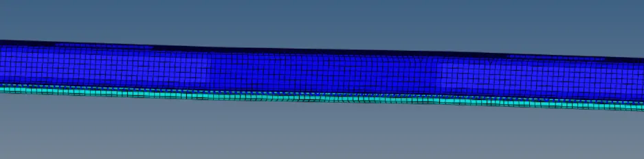
8. Left_Rail_1 & Left_Rail_2:- Spot-weld with Spring Elements
At both, the side free edges added spot weld with spring elements are added with a tolerance of 15
9. Rear Truss 2 & Left Rail 1:- Seam weld with quad elements
At the desired location we can use the connectors options in 2d panel and set quad elements at the required position
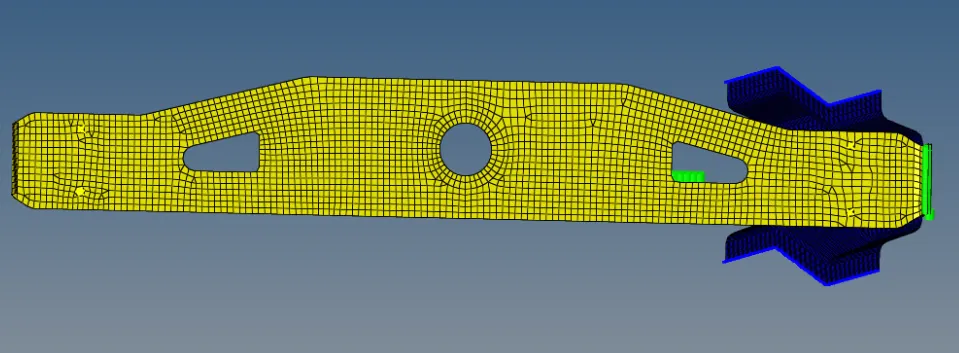
10. Front truss_1, Front truss 2 and Reinf _plate
At the desired location we connect it with spot weld elements
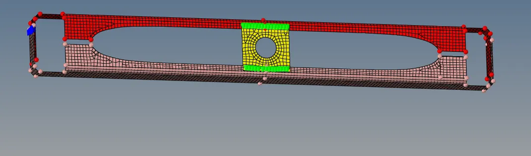
11. Rear Truss 1 and Rear Truss 2: Bolt Connector
At the desired location we connect both the components with bolt connections
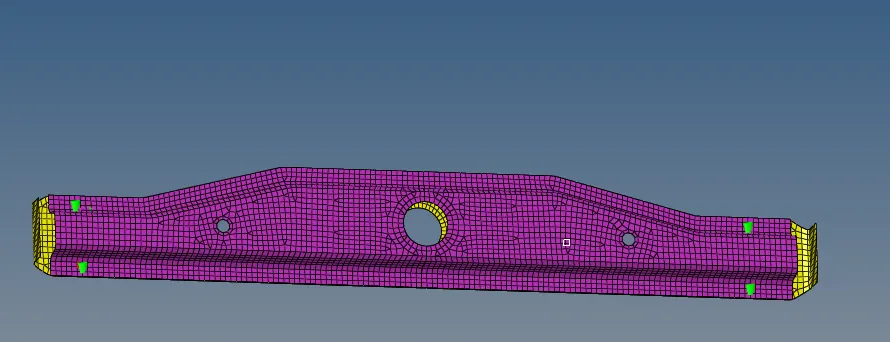
FINAL MODEL:
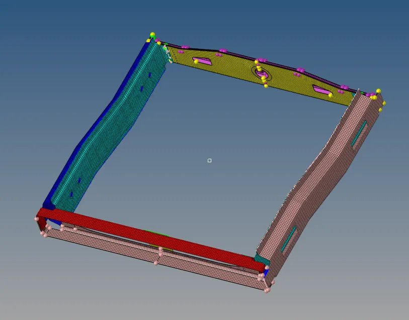
RESULTS:
The model is meshed and connectors was set between all components
LEARNING OUTCOMES:
Learned how to connect two components using various connectors