Sphere pressing on a plate
AIM:
For this challenge, we have to perform the analysis to simulate a sphere pressing on a plate and capture the region of plastic deformation
THEORY:
In engineering, deformation refers to the change in size or shape of an object. Displacements are the absolute change in position of a point on the object. Deflection is the relative change in external displacements on an object.
Plastic deformation is the permanent distortion that occurs when a material is subjected to tensile, compressive, bending, or torsion stresses that exceed its yield strength and cause it to elongate, compress, buckle, bend, or twist
This type of deformation is not undone simply by removing the applied force. An object in the plastic deformation range, however, will first have undergone elastic deformation, which is undone simply be removing the applied force, so the object will return part way to its original shape. Soft thermoplastics have a rather large plastic deformation range as do ductile metals such as copper, silver, and gold. Steel does, too, but not cast iron. Hard thermosetting plastics, rubber, crystals, and ceramics have minimal plastic deformation ranges. An example of a material with a large plastic deformation range is wet chewing gum, which can be stretched to dozens of times its original length.
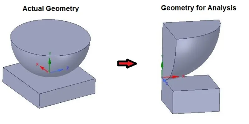
In case there is a symmetry region and we can mirror the results to other regions then that is more beneficial in terms of computational time. In this case we have a whole sphere and a flat plate. Here since the geometry has 2 planes of symmetry we use only a quarter of that
MATERIALS REQUIRED:
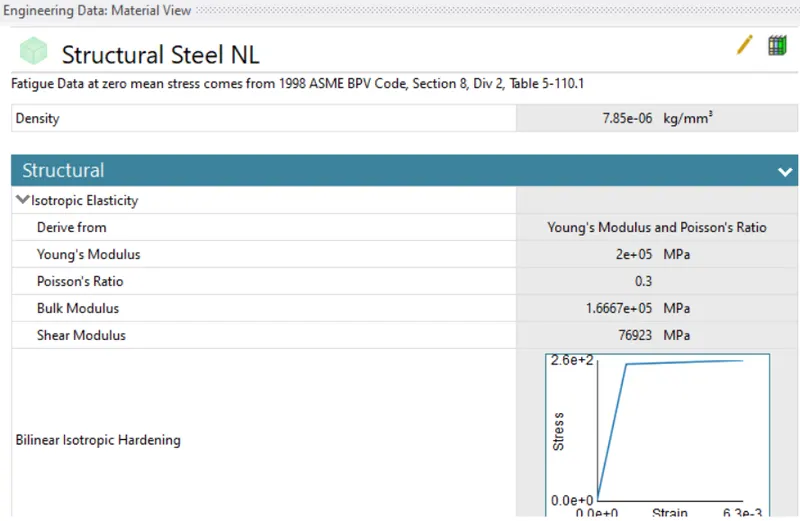
FOR PLATE
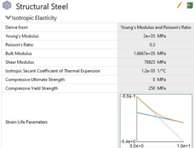
FOR SPHERE:
PROCEDURE
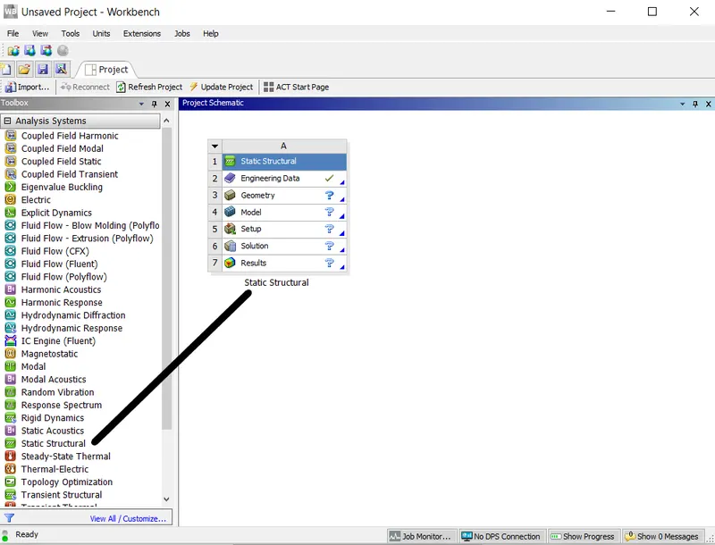
1. We first import the static structural module to ansys workbench. This can be done simply by dragging static structuraal into the workbench space
2. Import model in Static Structural named as "Skill_Lync_Sphere_pressing on plate.STEP" in Geometry section.
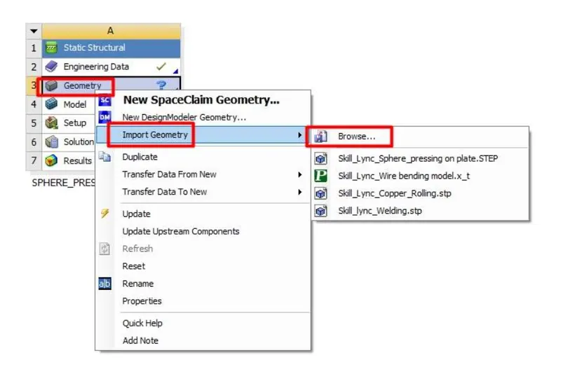
3. Now open the geometry in Ansys SpaceClaim to verify for any error or abnormalities in the geometry.Then go to the Mechanical model section.
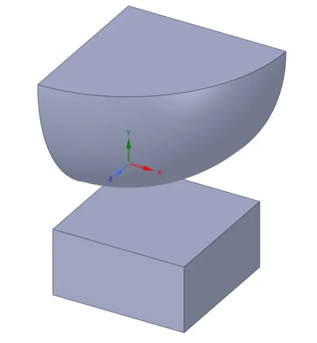
4. Check or Rename the Parts of the setup as "Sphere", and "Plate" as shown in above geometry image.
5. Sphere material is by default as Structural Steel. • Assign "Structural Steel N L material to Plate.
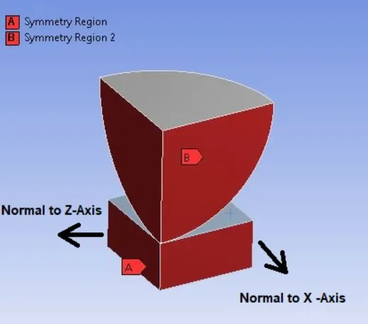
6. As we are only modeling a quarter part we have to give the symmetry option to trace the results for the full component
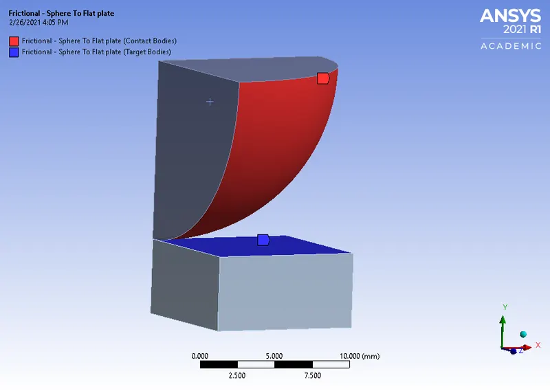
7. Now we have to set connections. We delete any default connection and set a frictional connection between plate and contacting surface of the sphere
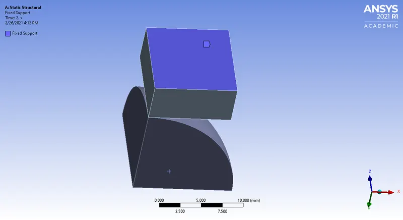
8. We apply a fixed support on the base of the plate to fix the plate for the analysis as shown below
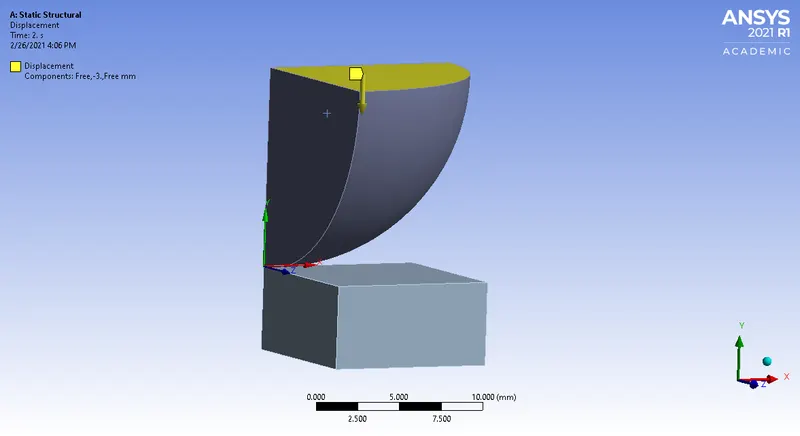
9. Now we give a displacement to the top of the sphere to captue the simulation. Here we give a 4mm displacement and later reduce it to zero to clearly capture the plastic deformation of the plate
10.After giving proper boundary conditions, we now create desired solutions for output results.
• Create Solutions for :
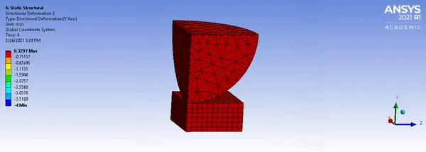
o Directional Deformation in Y-axis for the Whole Setup
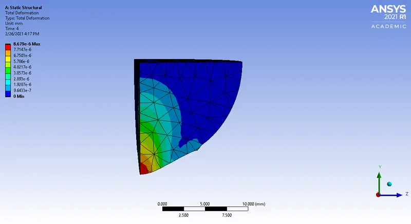
o Total Deformation on the sphere
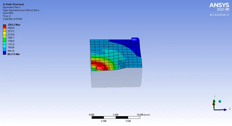
o Equivalent Stress For Plate
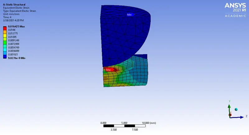
o Equivalent Strain For The Whole Setup
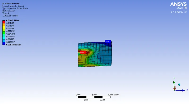
o Equivalent Plastic Strain for Plate
RESULTS:
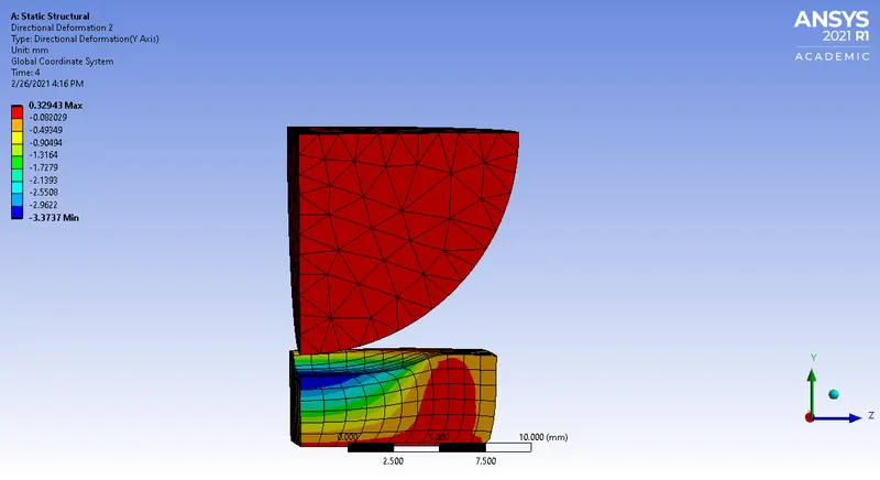
Directional Deformation in Y-axis for the Whole Setup
Total Deformation on the sphere
Equivalent Stress For Plate Top Surface
Equivalent Strain For The Whole Setup
Equivalent Plastic Strain for Plate
CONCLUSION
• The sphere pressing on plate simulation is performed successfully.
• The above simulation clearly shows that after the sphere retracts to its original position i.e., when loading is removed on the plate doesn't retain its original shape thus we can say that the plate undergoes plastic deformation.
• The sphere is pressed 4mm and retracted under simulation.
• The plastic deformation is captured successfully.