Wire Bending Simulation
AIM:
To perform an analysis to simulate the bending of a wire in ANSYS. You will have to use Copper Alloy (Non Linear), Aluminium Alloy (Non Linear) and Magnesium Alloy ( Non Linear) for the wire alone. You need to find out the Equivalent stress and Equivalent strain on the wire alone.
INTRODUCTION
Although there are many types of wire forming, in production wire forming specialized machinery is used. These wire 4-Slide Wire forming machines have many methods that can be employed to achieve the desired results however only a few are available to manufacture repeatable and fast results. In years past this was achieved through the use of machinery using CAM's to actuate benders (old technology). These CAM-operated 4-Slide machines required extensive setup, many trials runs and scrapped parts and large quantities to make it all that setup worthwhile. Today, using CNC technology, the new and highly modifiable machines form wire for hundreds of processes from rebar used in concrete forms to store racks & shopping carts along with millions of other parts in between even including jewelry. Although this manufacturing technology has been around for thousands of years it has become a very specialized and highly technical industry.
PROCEDURE:
We have to import the static structural analysis module into the workbench
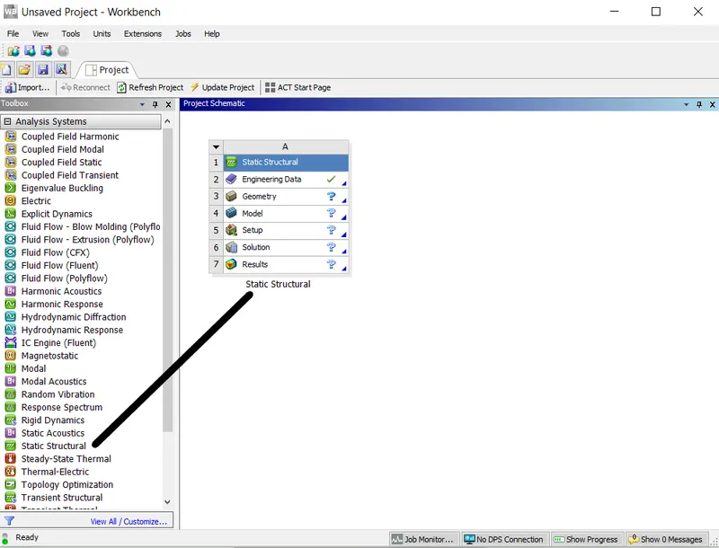
Double click on engineering data to add copper alloy(Non Linear), Aluminium Alloy (Non Linear) and Magnesium Alloy ( Non Linear)

MATERIAL PROPERTIES
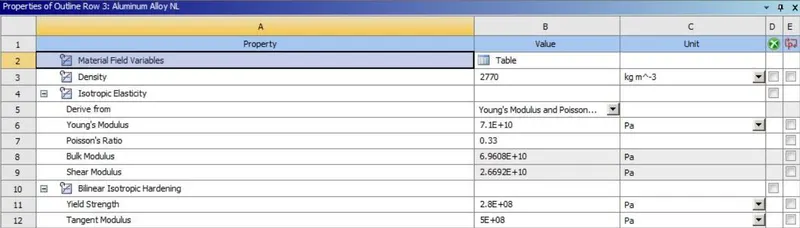
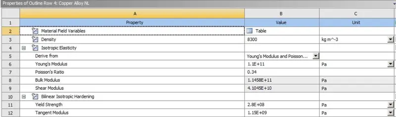
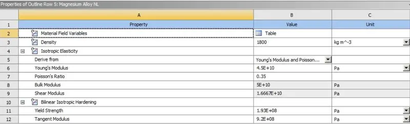
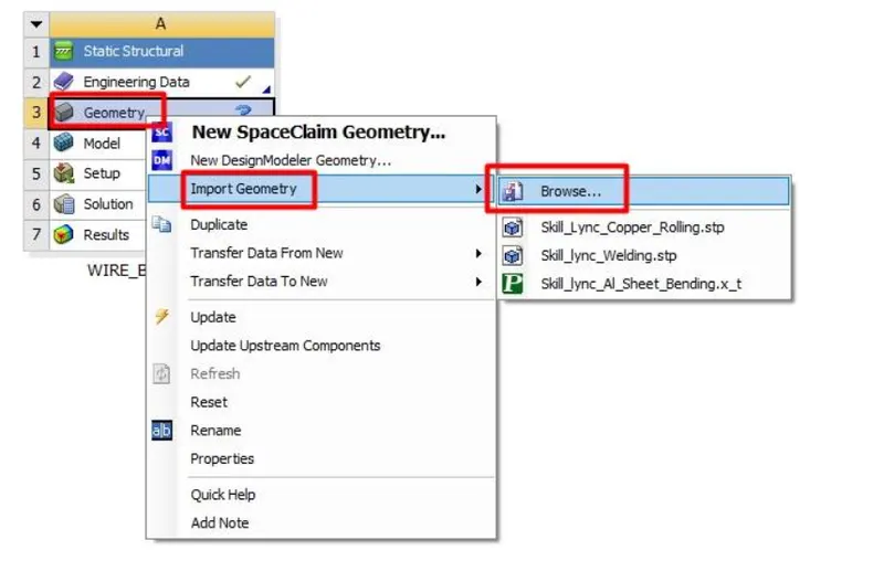
Import the geometry by browsing through the Geometry--> Import Geometry-->Browse
Open the geometry in Spaceclaim to check for any errors or abnormalities
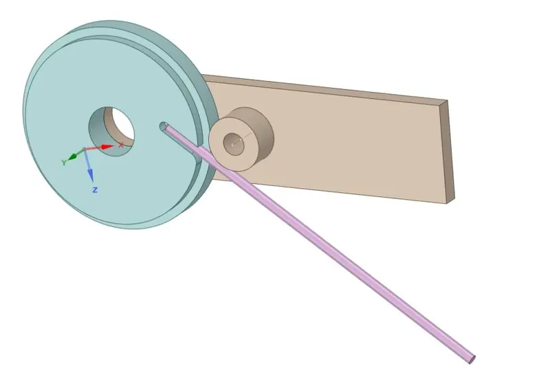
• Open ansys mechanical rename the geometry as require.
• Change the material for the wire as Copper Alloy (Non-Linear).
• Go to connections and right-click on the contact group and click on rename based on the definition.
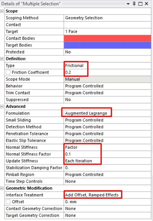
• Delete all the contact and create the contacts between wire and lever and wheel to wire as below.
• Change contact type to frictional with a coefficient of friction of 0.2 and change formulation to augmented Lagrange and update normal stiffness by a factor of 0.1 and update stiffness for each iteration.
• Change interface treatment to add offset, ramped effects.
• The above graph represents the mesh metrics which gives mesh quality and element type.
• Now change the analysis setting change number of steps to 8 and turn on the auto time-stepping and change the analysis settings for step-1 as below. change solver type to direct and turn on the large deflection. Change all the output controls to yes.
Details of "Analysis Settings"
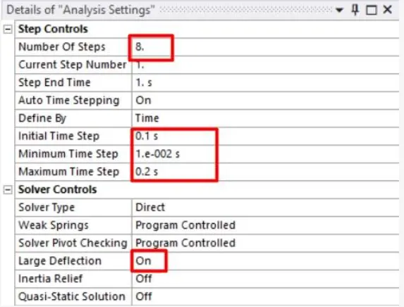
Number Of Steps 8. Current Step Number Step End Time 1. s Auto Time Stepping On
Define By Time
Initial Time Step 0.1s
Minimum Time Step 1.e-002 s
Maximum Time Step 0.2 s
Solver Controls
Solver Type Direct
Weak Springs Program Controlled
Solver Pivot Checking Program Controlled
Large Deflection On
Inertia Relief Off
• Now select steps2-8 and change the analysis setting as below.
• Create fixed support for the wheel and the end of the wire as shown below.
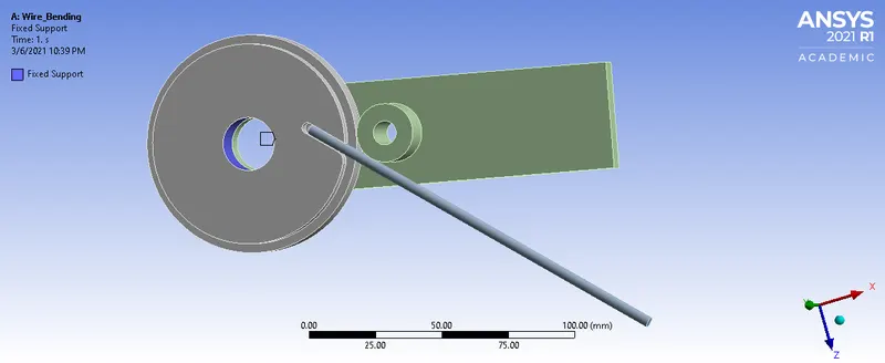
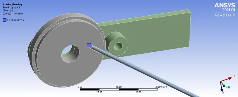
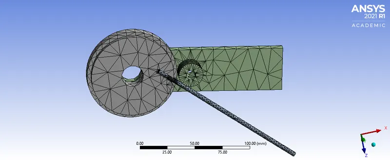
Now we mesh the components. We give faces sizing mesh option at areas of contact and all other regions normal is used
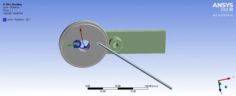
Now we define a rotation to the wheel. We give a rotation of 20-degree and increment it respectively
CASE 2: Now we change the wire material to aluminium alloy and follow the same procedures
CASE 3:Now we change the wire material to magnesium alloy and follow the same procedures
RESULTS:
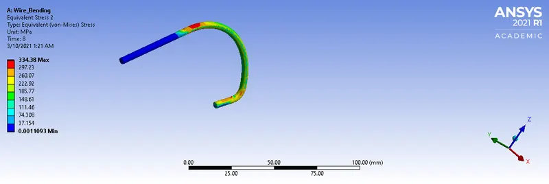
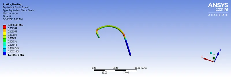
Copper Alloy NL
Total Deformation

Von-mises Stress for the wire
Equivalent Strain for the wire
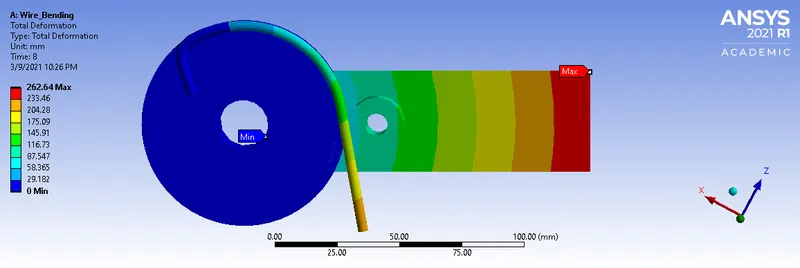
Magnesium Alloy NL
Total Deformation
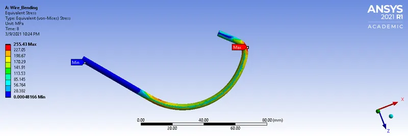
Von-mises Stress for the wire
Equivalent Strain for the wire
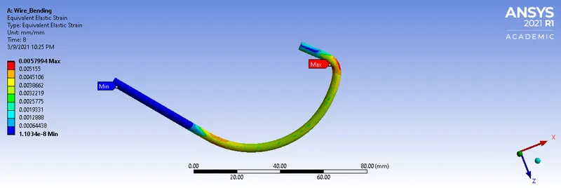
Aluminium Alloy NL
Total Deformation
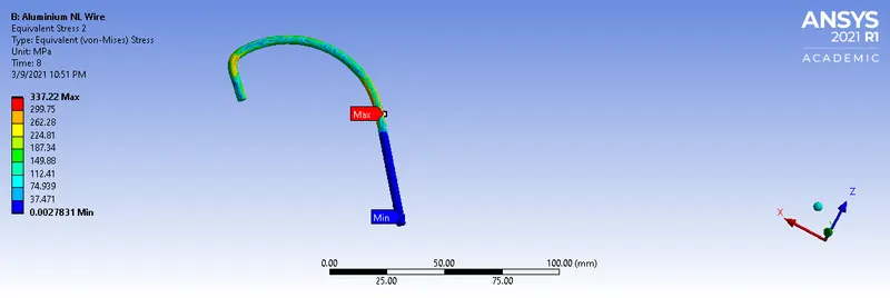
Von-mises Stress for the wire
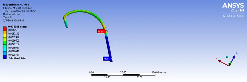
Equivalent Strain for the wire
CONCLUSION:
| Material | Equivalent Stress | Equivalent strain |
| Copper Alloy NL | 262.64 | 0.003 |
| Aluminium Alloy NL | 337.22 | 0.0047883 |
| Magnesium Alloy NL | 255.43 | 0.005 |
Aluminum alloy experiences the highest von mises stress
Magnesium alloy experiences the maximum equivalent strain