Grid dependency test for the Bevel gear simulation
AIM:
Perform a grid dependency test for the Bevel gear simulation for mesh sizes of 6,5 and 4 mm
INTRODUCTION:
Bevel gears are gears where the axes of the two shafts intersect and the tooth-bearing faces of the gears themselves are conically shaped. Bevel gears are most often mounted on shafts that are 90 degrees apart, but can be designed to work at other angles as well. The pitch surface of bevel gears is a cone.
Bevel gears are classified in different types according to geometry:
- Straight bevel gears have conical pitch surface and teeth are straight and tapering towards apex.
- Spiral bevel gears have curved teeth at an angle allowing tooth contact to be gradual and smooth.
- Zerol bevel gears are very similar to a bevel gear, but the teeth are curved: the ends of each tooth are coplanar with the axis, but the middle of each tooth is swept circumferentially around the gear. Zerol bevel gears can be thought of as spiral bevel gears, which also have curved teeth, but with a spiral angle of zero, so the ends of the teeth align with the axis.
- Hypoid bevel gears are similar to spiral bevel, but the pitch surfaces are hyperbolic and not conical. The pinion can be offset above or below the gear center, thus allowing larger pinion diameter, longer life, and smoother mesh. If the beveled surface is made parallel with the axis of rotation, this configuration resembles a worm drive. Hypoid gears were widely used in automobile rear axles.
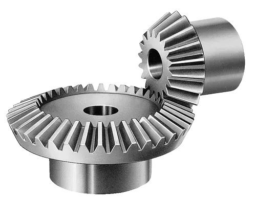
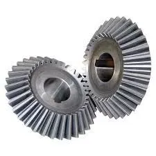
BEVEL GEARS
THEORY:
Grid Dependency Test: Mesh Size and Refinement is one of the most important considerations taken during Finite Element Analysis and the quality of Mesh depends on it. It directly affects the accuracy of any simulation, the higher the mesh density(or lower the mesh size) the higher the accuracy of the results. This would suggest that every simulation should be run with the lowest mesh size available but a lower mesh size increases the computation time of the simulation.
Practicality suggests reducing the mesh size until there is very negligible variation in between to results or the results converge. This process is known as Grid Dependency Test or Mesh Refinement Test. As mesh size approaches 0, the approximate solution and the actual solution converges
The main goal of this test is to achieve an efficient mesh size that isn't coarse enough to provide accurate results yet not fine enough that computation time is low.
PROCEDURE
1. First, we open the Ansys workbench and import the static structural module, and set up the necessary engineering data
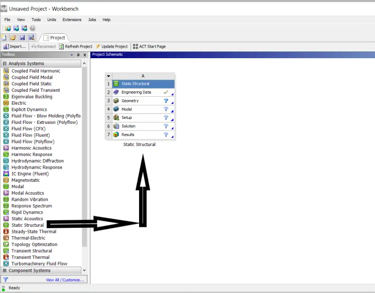
STATIC STRUCTURAL MODEL OPENED IN ANSYS WORKBENCH
2. To perform this test we run the simulation with the same exact analysis settings and parameters for 6mm, 5mm and 4mm. The assigned material is Structural Steel whose density is 7850kg/m^3, Youngs Modulus is 200GPa. Poisson's Ratio is 0.3. Yield Strength is 250MPa and Ultimate tensile strength is 460MPa.
We set up the geometry in SpaceClaim and we pull out the unnecessary parts to fit the nodes to the academic version limits.
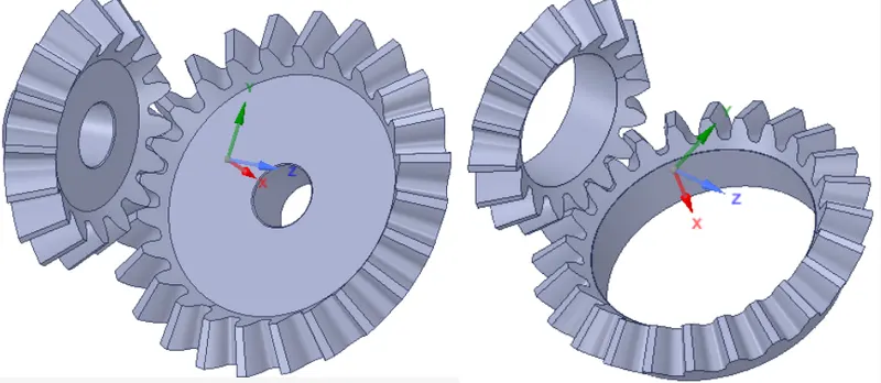
3. The material used here is Structural Steel and it has the following properties. It can be check in the materials section in the mechanical module
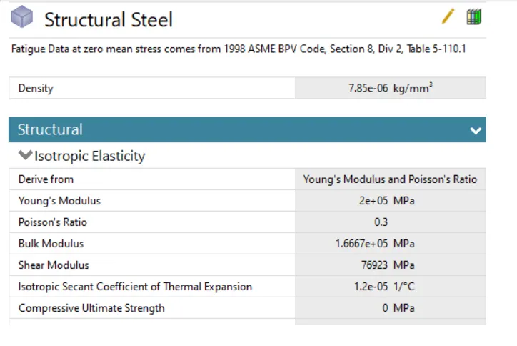
MATERIAL CARD DEFINITION
Now we have to set the contact between the gears. Here we give a frictional contact. First, for the sake of simplicity, the gears are named as 'Small' and 'Big according to their sizes. Then, contact between all both the gears is defined with the following settings-
Type: Frictional
Behavior: Symmetrical
Formulation: Augmented Lagrange
Interface Treatment: Adjust to touch
Augmented Lagrange In the analysis, a relation must be established between two surfaces to prevent them from passing through each other. Augmented Lagrange or Pure Penalty is preferred for non-linear solid body contact faces. Augmented Lagrange: Fnormal = knormal XPenetration + λ
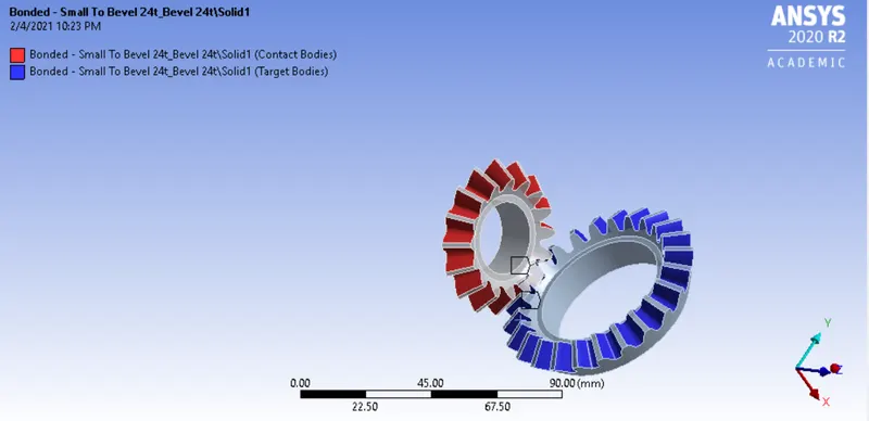
CONTACT DEFINITION FOR BEVEL GEARS
Two joint loads are defined Static Structural-->Insert-->Joint. The small gear is given 20 degree increment upto 120 for rotation and the large gear is given a moment of 100
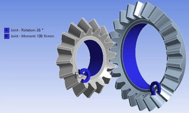
JOINT DEFINITION FOR BEVEL GEARS
The following steps were applied for analysis:
No. of steps-6
Auto Time Setting-ON
Defined By-Time Initial Time Step-0.2s
Maximum Time Step-1s Minimum Time Step-0.1s
Large Deflection: ON
Now we mesh the components. For mesh, a local face sizing of 1.75mm on the teeth of both the gears is applied since that is the area of interest from where results will be obtained. This is carried out to obtain accurate results along with the global mesh size.
The Sizing can be inserted by right-clicking on the Mesh—Insert—Sizing. Whenever the user wants to improve or just change the element size for a specific model or a part of a model instead of trying to change the mesh for the whole body, the Mesh sizing is used.
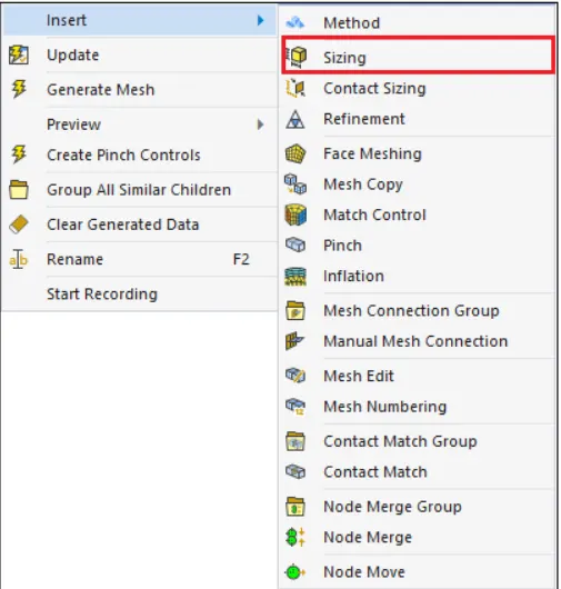
MESH-->INSERT-->SIZING
The Mesh Sizing can be used to set the following: • The element size for a selected body, face, or edge. • The number of divisions along an edge • The scale factor for a selected body, face, or edge
The following picture shows the mesh at 6mm element size and a face sizing of 1.75mm on the teeth. We can also check the mesh metric by Quality-->Metric-->Element Quality
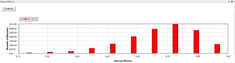
MESH METRIC
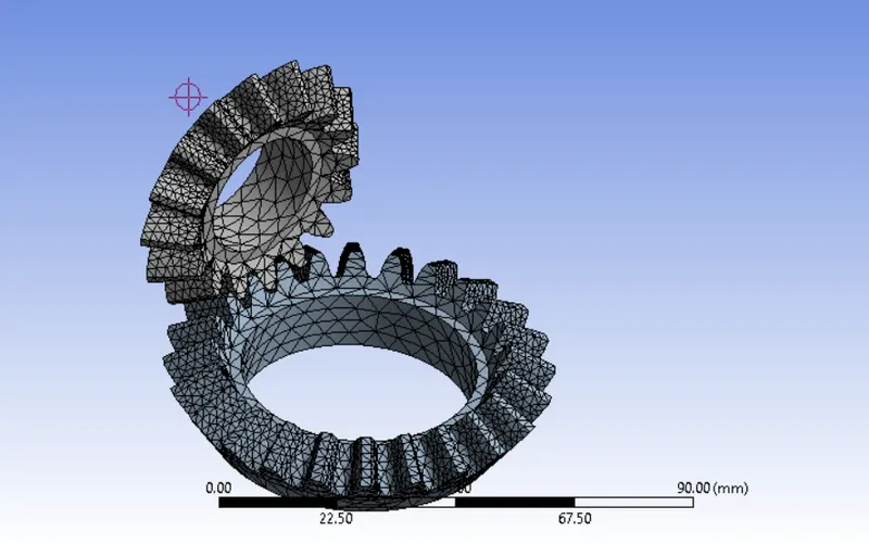
BEVEL GEAR MESHED MODEL
Now we have to request the respective outputs in the solution block and then we run the analysis
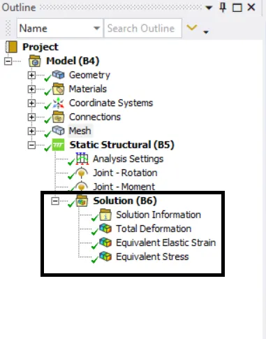
OUTPUT BLOCKS
RESULTS
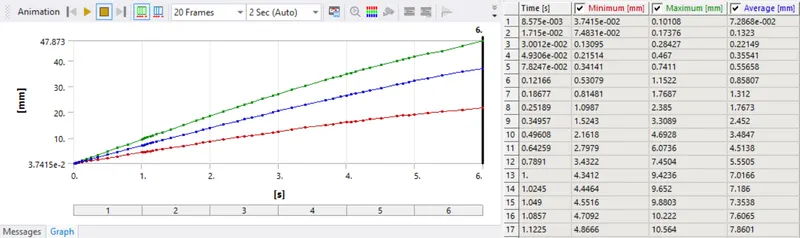
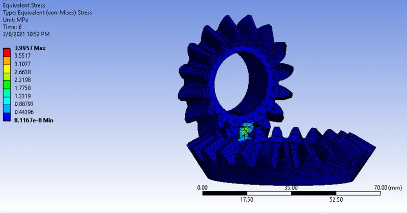
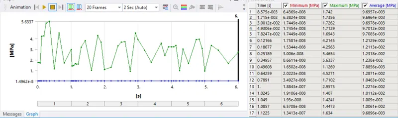
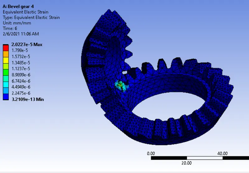
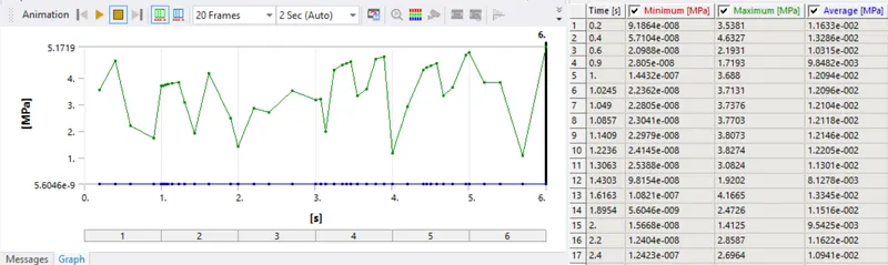
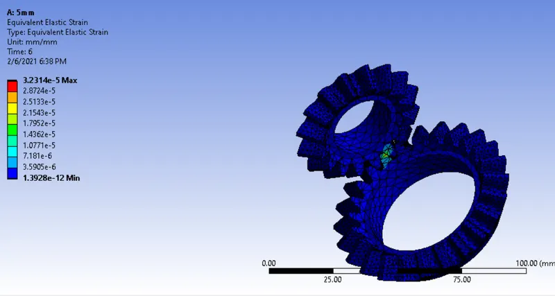
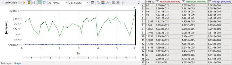
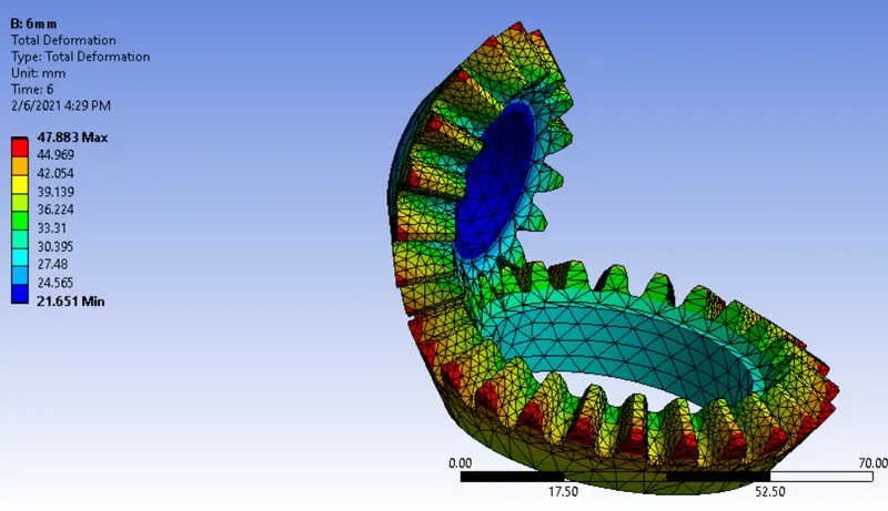
The contours and graphs of various mesh sizes and their respective outputs can be seen below
CASE I: 4mm Mesh Size
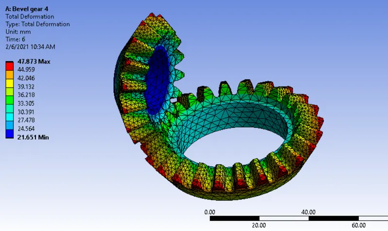
TOTAL DEFORMATION
VON MISES STRESS
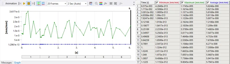
EQUIVALENT STRAIN
CASE II: 5mm Mesh Sizing
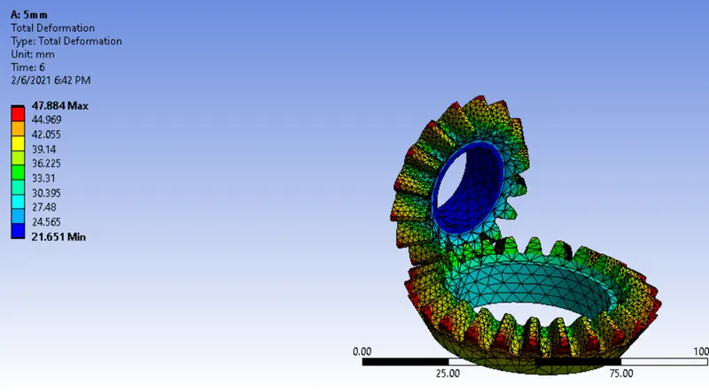
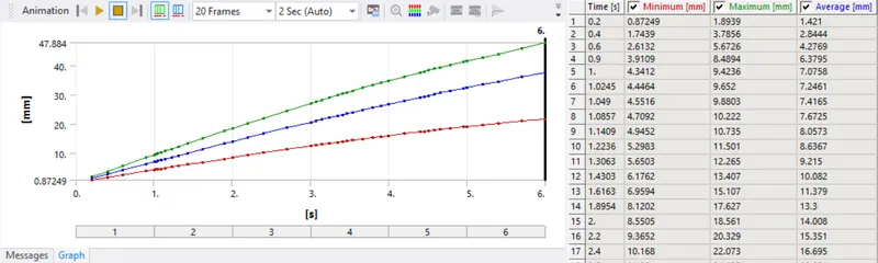
TOTAL DEFORMATION
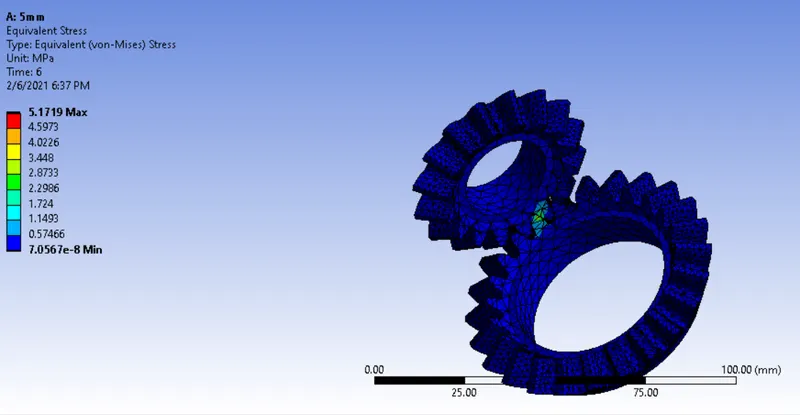
VON MISES STRESS
EQUIVALENT STRAIN
CASE III-6mm Mesh Size
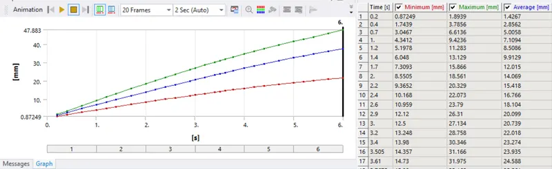
TOTAL DEFORMATION
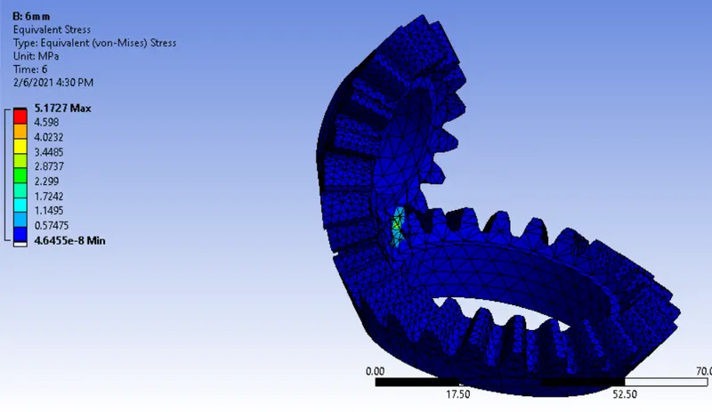

VON MISES STRESS
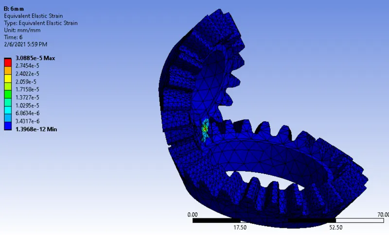
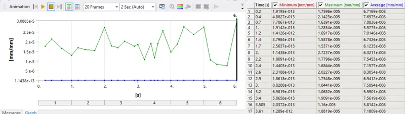
EQUIVALENT STRAIN
| MESH SIZE | DEFORMATION[mm] | VON MISES STRESS[MPa] | STRAIN |
| 4mm | 47.873 | 3.9957 | 3.233E-05 |
| 5mm | 47.884 | 5.1719 | 3.2314E-05 |
| 6mm | 47.883 | 5.1696 | 3.233E-05 |
CONCLUSION:
As expected from the Grid dependency test, as the mesh was changed from coarse to fine, the accuracy and the results too improved. It can be seen from the first table that there was a significant improvement in results for Equivalent Stress and Equivalent Strain and Deformation nearly tend to remain constant.
It is also observed that when the mesh was made finer to 4mm, a significant change in Equivalent Stress result was observed and for values below that it remained constant which means that Grid Independence has reached and further the results are not dependent on Grid size or element size anymore and further reducing element size is unnecessary as values tend to remain same nearly.
If the mesh size is further reduced, it will only increase computational time. Therefore, it can be said that the optimal mesh size is 4mm.
You can find the simulation files here