Stress Concentration on a Plate with hole
1. Objective:
This challenge makes us know which design is better as per the results of the analysis as well as the manufacturing point of view.
Determine the maximum deformation and stress developed in the model.
Compare both the results and select suitable results
Steps to be taken during the analysis
1- Open the Ansys Workbench.
2- Select the proper engineering data (material)
3- Create a geometry.
4- Mesh the geometry.
5- Give the boundary conditions.
6- Apply the solver to solve.
7- Results analysis.
PROCEDURE:
CASE I:
First, we open the Ansys workbench and import the Static structural module
Using SpaceClaim a 2D sketch was made of a rectangle with a circular cut out in the middle
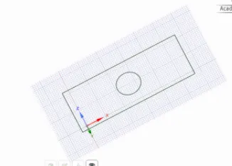
We use the PULL option to extrude the 2d surface to make it into a 3d solid and delete the surface part
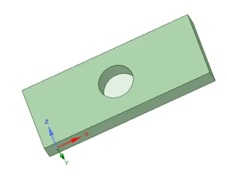
We then close the SpaceClaim modeler and it gets saved to the selected dataspace. We then move on to the Model Option
This is the material we have defined for the model
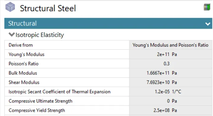
Material Definition
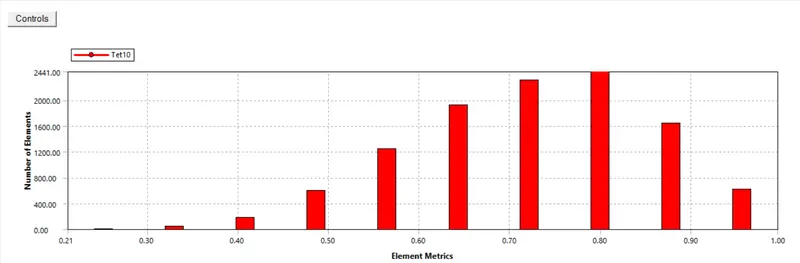
Now we have to mesh the given component.A Mesh is a network that is formed of cells and points. Meshing is a part of the engineering simulation manner where complex geometries and models are divided into simple elements that can be used as discrete local approximations of the larger domain..Here we use a mesh size of 4mm to stay within the node limit of ANSYS student version
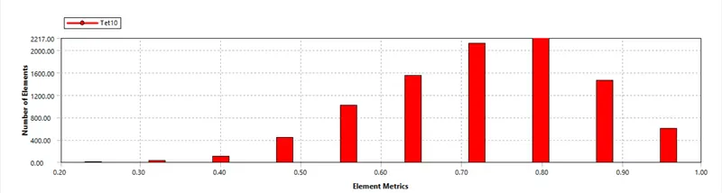
Mesh Quality
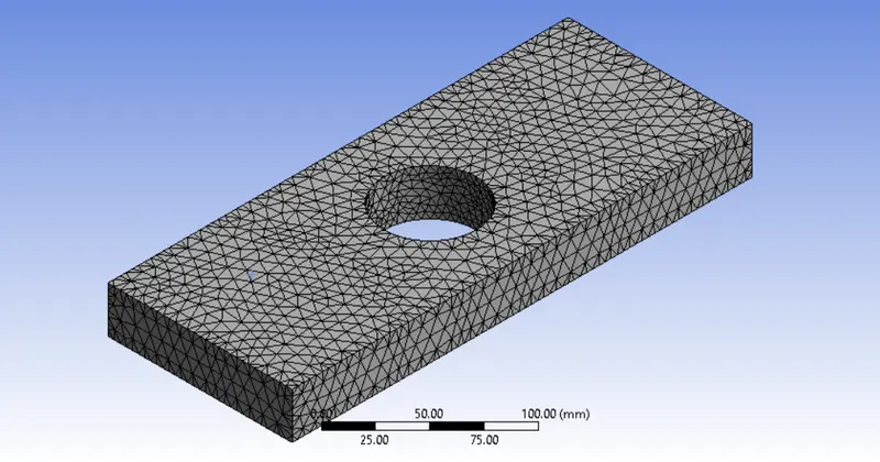
Meshed Model [4mm]
Now we have to setup the boundary conditions.The left-face was given fixed support and in the right face, a force of magnitude 500N was given.
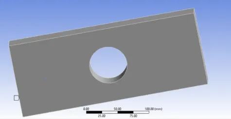
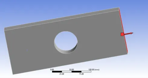
Fixed Support 500N Force applied
This was a schematic diagram of the model for which the analysis is to be performed can be viewed below
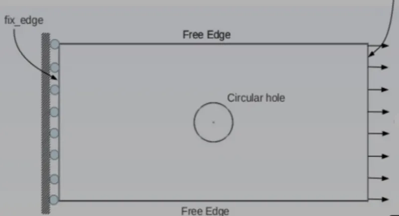
Now we have to request the needed outputs in the solution panel through Solution-->Insert
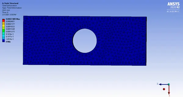
Total Deformation
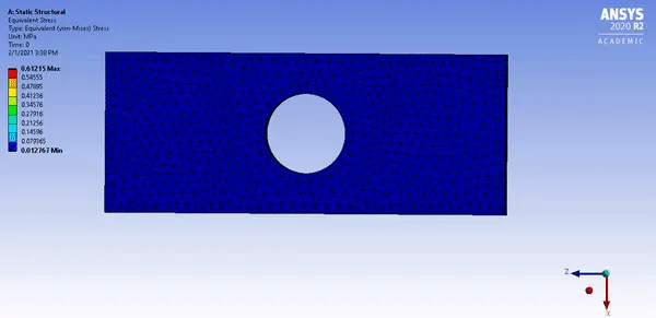
Von Mises Stress Contour
CASE II:
We open SpaceClaim construct the rectangle the same as previous dimensions and create two additional holes and pull the model.Here we will analyze the case of a plate with 3 holes
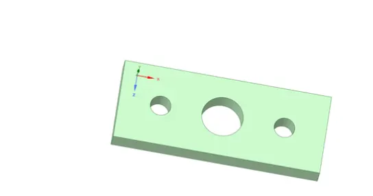
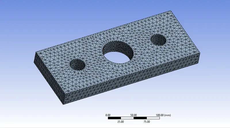
Similar to the previous case here also we setup the boundary conditions and request the needed outputs in the solution panel
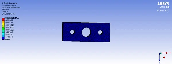
Total Deformation animation
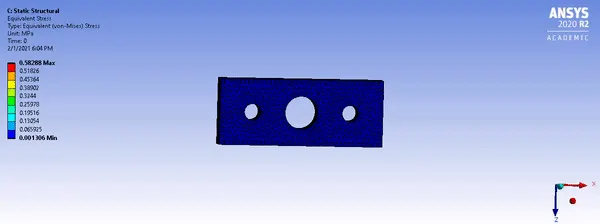
Von mises stress animation
RESULTS:
CASE I
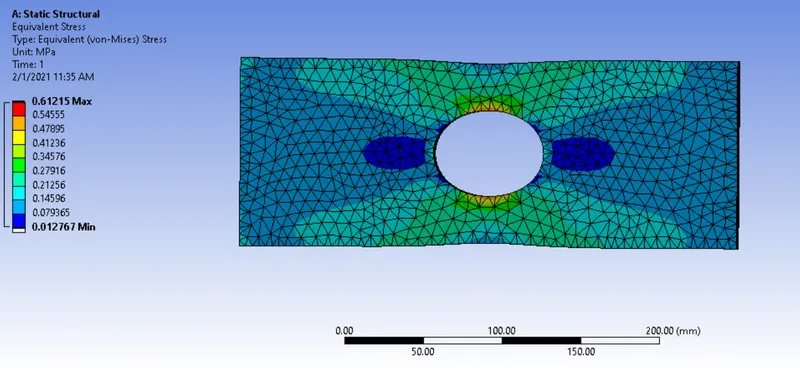

Von Mises Stress
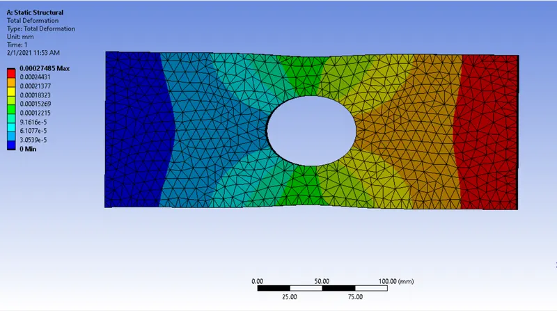

Total Deformation
CASE II:
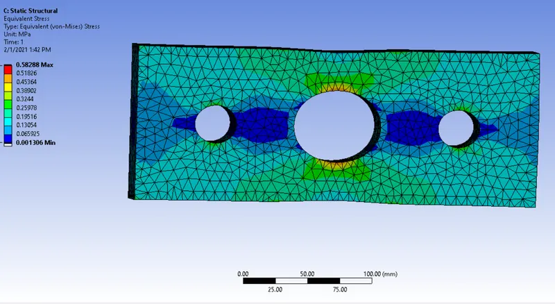

Von mises stress contour
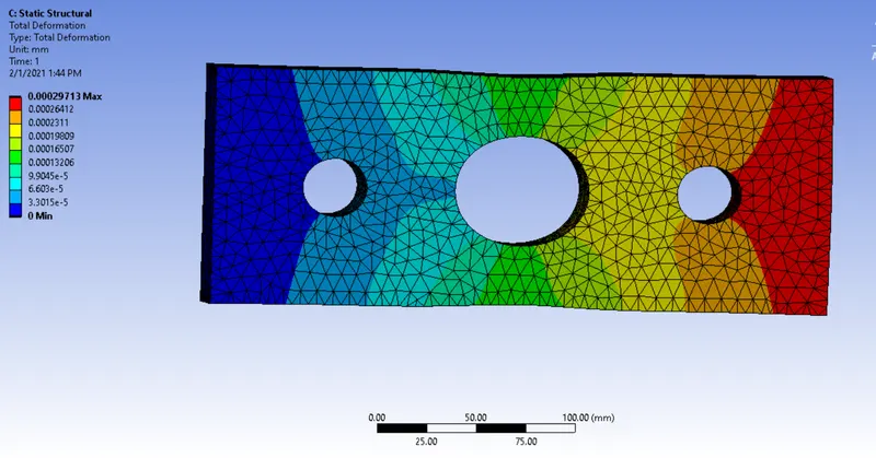

Total Deformation
Conclusion:
There is a difference in the average stresses about 0.00754,the average stress being higher in the Case1 by a marginal difference, because the surface area being interrupted with many holes leads to an increase in stress concentration due to reduction in surface area,the difference in average deformation is about 0.0081 microns, maximum deformation being higher in case 2.
From a manufacturing point of view, its easier to punch one hole at the center (Casel) rather than mark and punch the plate at three different positions(Case 2), making holes in the plate leads to an increase in stress concentration so punching multiple holes from a manufacturing point of view isn't recommended because it might break the plate
From an analysis point of view CASE 2 is preferred because the stresses induced are comparatively lesser in magnitude compared to Case l and is distributed much uniformly around critical regions due to the presence of 3 holes