Roof crush analysis as per FVMSS 216 standards
OBJECTIVE:
To set up and run a Quasi-static Roof crush analysis on a reduced model of a Neon car as per FMVSS 216
Introduction :
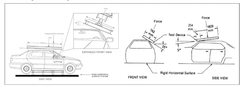
Roof crush simulation Federal Motor Vehicle Safety Standard No. 216 (FMVSS 216) first published in 1971 specified the test requirements and configurations of Roof crush process. The roof strength is measured by the resistance force required to push a rigid plate into the roof structures. According to the latest version of FMVSS 216, the reaction force (RF) is increased from 1.5 times of unloaded vehicle weight to 3 times. The test plate locates with roll angle 25 and pitch angle 5. The initial contact point is on the longitudinal centreline of the lower surface of the test device, 254 mm from the forward-most point of that centreline. Then the test device is applied to move in the downward direction perpendicular to the lower surface.
The Test configurations of the regulation.
PROCEDURE:
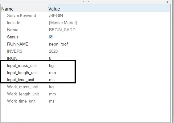
1. Solver-deck set-up 1. Import the reduced model of Neon into Hypercrash. The unit system chosen is Kg, mm, ms, kN.
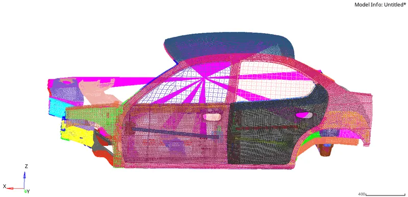
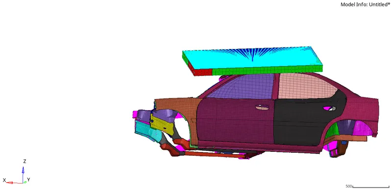
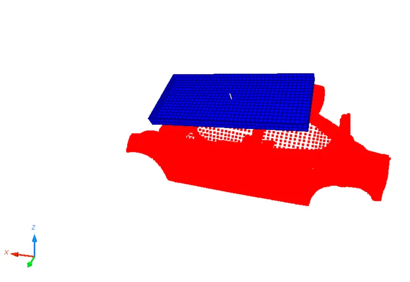
2. We then import the impactor for the roof crush and apply the necessary translations and bring to the required position. The test plate is aligned using industry standards
3. We now verify the unit consistency either by checking the Begin card or the checking the Radioss starter file
4. Now we setup the contact interface by setting up type 7 contact interface
Igap(Determines how the size of the gap is calculated): 3 Variable gap + gap scale correction of the computed gap + size of the mesh is taken into account to avoid initial penetrations during self-contact.
Fscale_gap(Gap scale factor) : 0.8
Gapmin(Minimum gap for activation of the interface ): 0.5
Inacti(Action to take if initial penetrations exist): 6 Gap is variable with time but initial penetration is computed Istf(Affects how the stiffness of the interface is calculated): 4
Kmin=(Km, Ks) Iform(Friction formulation): 2 Stiffness
Stmin(Minimum stiffness to use in the interface): 1
Idel(What to do with slave nodes and master segments if an element fails (deleted) that they are attached to): 2 when a element is deleted, the corresponding segment is removed from the master side of the interface
Fric(coefficient of friction ): 0.2
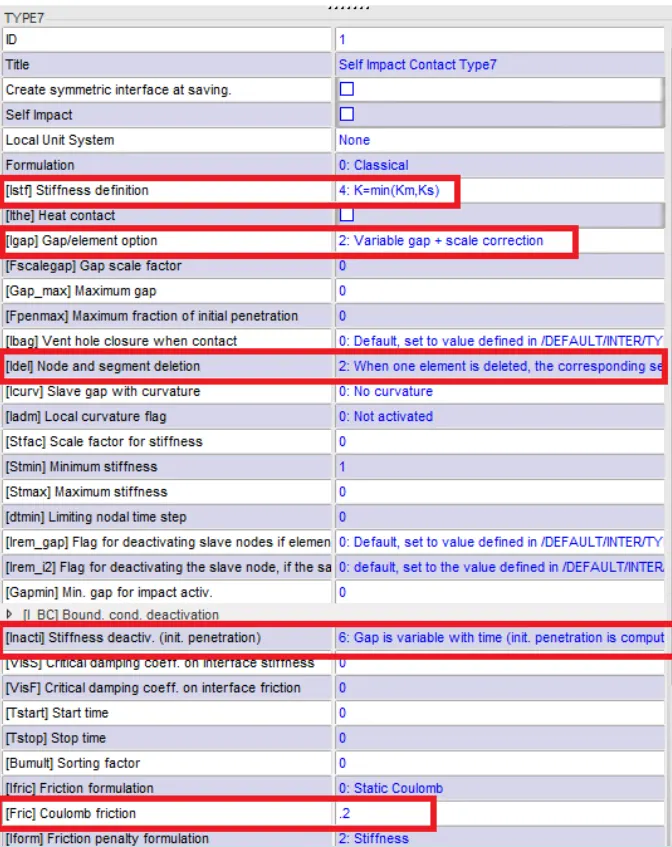
Type 7 contact interface with recommonded parameters
5. Similarly we define type 7 contact interface between the impactor and car model. Here blue nodes indicate the master segment and red indicates the slave nodes
II.Boundary conditions
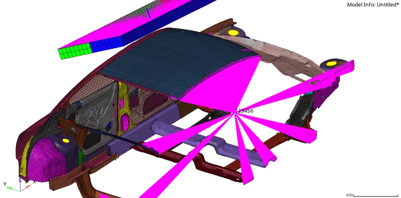
1. The impactor assembly contains a spring attached for stability. We create a BCS collector to fix the free end of the spring hence we can measure the elongation of the spring
2. To keep the suspension tower nodes locked in z-direction go to 1D»rigids»elem type = RBE2» multiple nodes» calculate nodes»select nodes by path»give the necessary dof (uncheck dof3 and dof6)»create. The figures are shown below. We also assign a BCS to the rigid section
3. Moving Skew definition
We then define a moving skew such that z axis of the impactor faces the car. We deine the skew using Create-->SKEW-->MOV
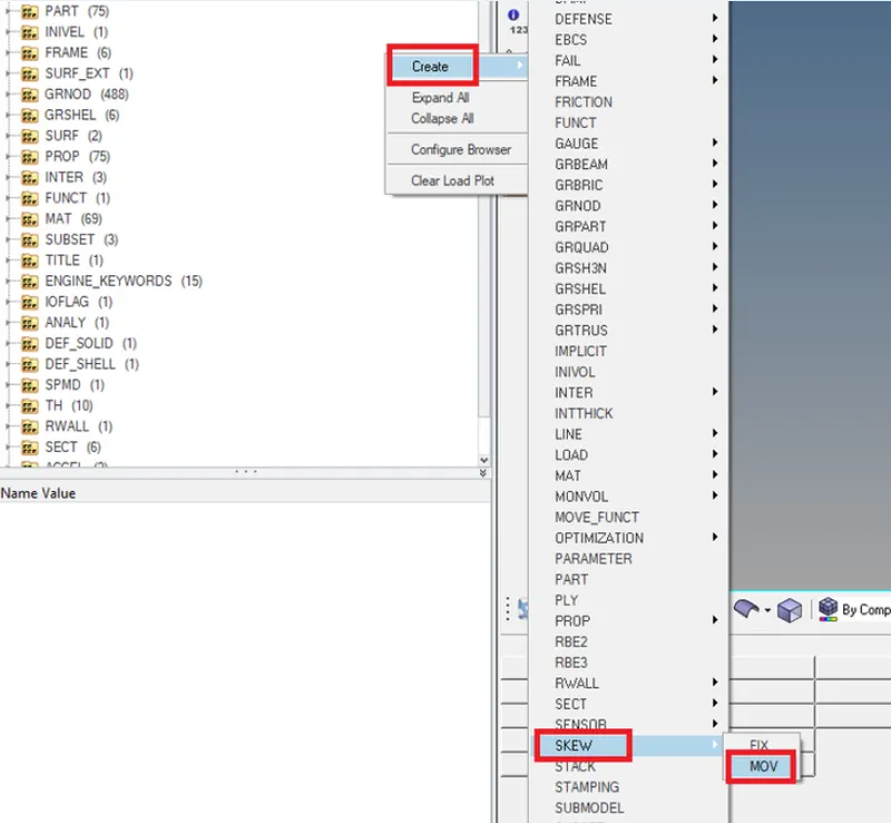
Create-->SKEW-->MOV
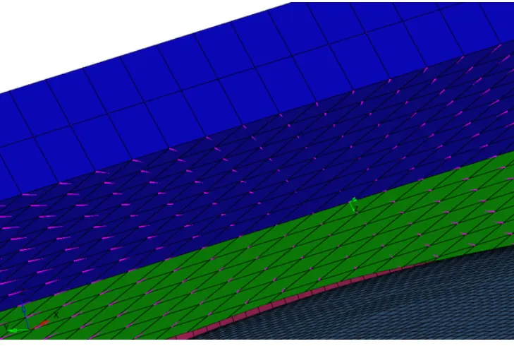
Moving skew defined
4. Control Cards Definition
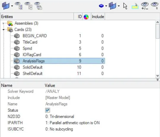
Iparith =1 Parallel arithmetic option is ON. The Parallel arithmetic flag is set ON, the same numerical results will be obtained irrespective of the number of processors used. This result is not guaranteed in case of incompatible kinematic conditions in the model
• /DEF_SHELL card, ( This keyword is used to set default values for certain parameters in all shell properties, but options could still be changed in each property set input and in this case, the latter will prevail.)
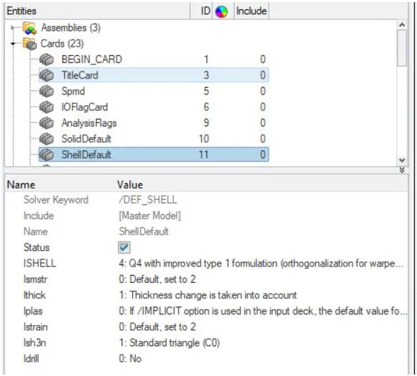
lSHELL : 4-04 with improved type 1 formulation (orthogonalization for warped elements)
Ismstr : 2-(default) Full geometric nonlinearities with possible small strain formulation activation in Radioss Engine
lthick : 1-Thickness change is taken into account.
Iplas : 0-Default if /IMPLICIT is not used in deck.Radial return lstrain : 2-No Ish3n : 1-Standard triangle (CO) !drill : 0-Default if /IMPLICIT is not used in deck [No]
• /DEF_SOLID card
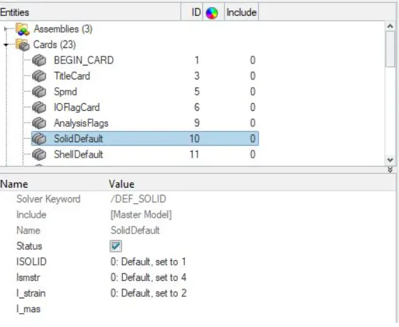
ISOLID : Standard 8-node solid element, one integration point. Viscous hourglass formulation with orthogonal and rigid deformation modes compensation (Belytschko).
Ismstr : Full geometric nonlinearities (/DT/BRICK/CST has no effect).
l_strain : No
• /IOFLAG card Describes the input-output flags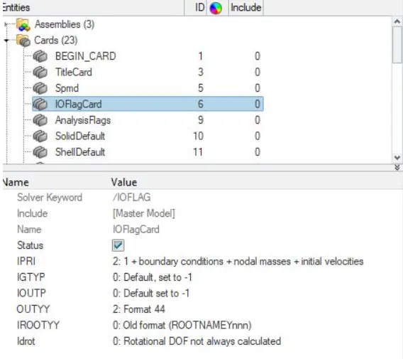
IPRI(Starter output printout flag) : 2 -1 + boundary conditions + nodal masses + initial velocities
IOUTP Output a STY model file flag): -1 - Do not output STY model file
OUTYY(STY file output format flag) : 2 Format 44
IROOTYY(STY file name flag) : 0-Ynnn writing file format is RunnameYnnn (old format IDROT(Force computation of rotational DOF flag): 0-Rotational DOF not always calculated
./SPMD Card: Sets SPMD parameters for hybrid Massively Parallel Program computation
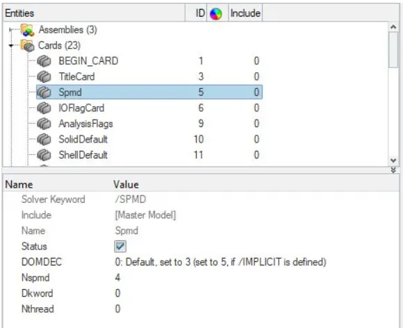
DOMDEC(Type of domain decomposition for SPMD version ) : 3 Multilevel Kway decomposition
Nspmd (Number of SPMD Domains) : 4
5. Imposed Displacement:
• To move the impactor towards the vehicle continuously until the end of the simulation, a displacement had to be imposed on it. For this, an 'IMP DISP' card was created from the 'solver>create new> boundary conditions>IMPDISP'.
• The function for this imposed displacement card was a linear function, starting at t=0 with 0mm displacement till t=200 with the complete 200mm displacement. For the frame of reference, the skew which was created on the impactor before was selected, and the direction of the imposed displacement was set as Z. The image below shows the IMPDISP curve and card created on the impactor.
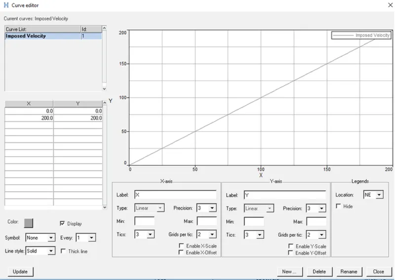
Curve definition tab
6. Model Checker
Now after defining the parameters we check the model for any error. Goto Tools-->Model checker-->Radioss for checking any errors in the model. All the errors were cleared and we move forward
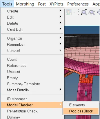
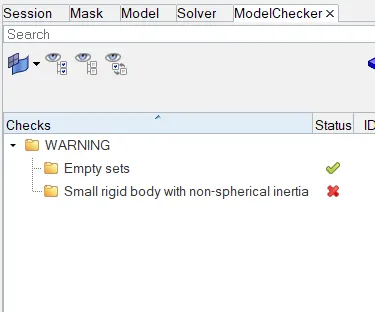
Model Checker-->Radioss Model Checker tab
7. Outputs Blocks
We assign the outputs required to the TH/output block. Output blocks can be defined by Model -->Create-->Output blocks
8. Engine Files
We then define the nodal time step and then the required Tstop and T freq values using Model-->Cards--> ENG_ANIM_DT and Model-->Cards--> ENG_RUN-->Tstop and respectively the other engine parameters as defined below
- Termination Time: 200ms
- The constant nodal time step is Used With T_scale : 0.67 and T_min:0.001
- Print time history for every 0.0001 seconds
- Animation file is created for every 0.005 seconds
9. Verify once again the model is error-free. Then goto Analysis-->Radioss--> options--> -nt 4-->Radioss and run the analysis
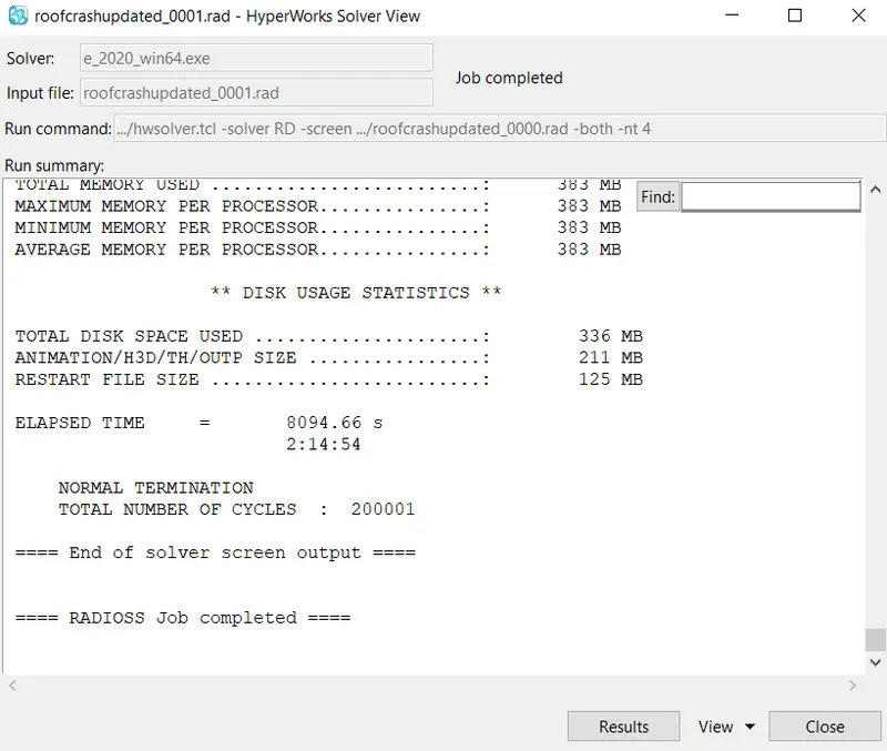
Hyperworks Solver Window
After successful completion of the run open the radioss engine out file and check for errors. Mass error should lie within ~3% and energy error should lie within (5 to -15%).We find that errors are well within the range. Hence here the results are acceptable. As the error is negative, it means that some energy has been dissipated.Now we move forward for post-processing of the results
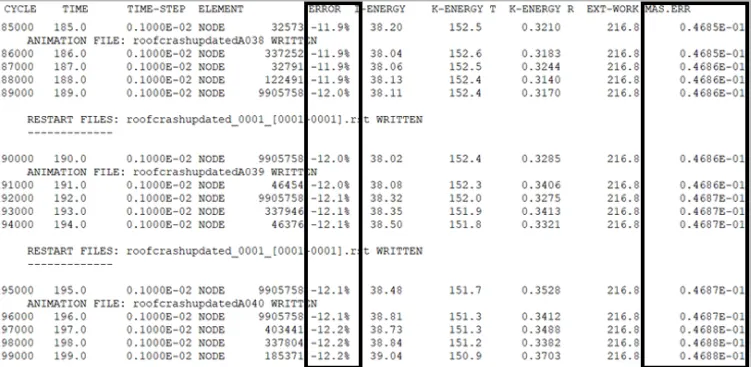
Output File
RESULTS:
The animation shows an impactor pressing against a car thereby applying a quasi-static load on the car. The car can be seen deforming
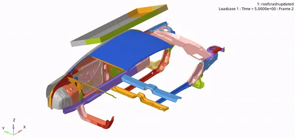
Crash Animation
A displacement contour is generated below. An imposed displacement of 200mm is applied on the impactor
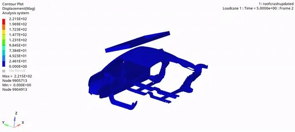
Displacement Contour
The von mises contour clearly shows the stress developing the car as the impactor is hitting it
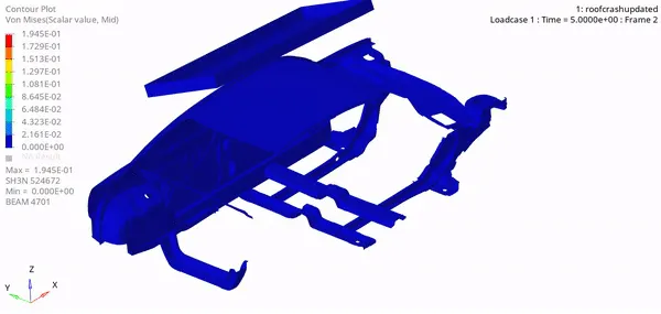
Von-mises stress
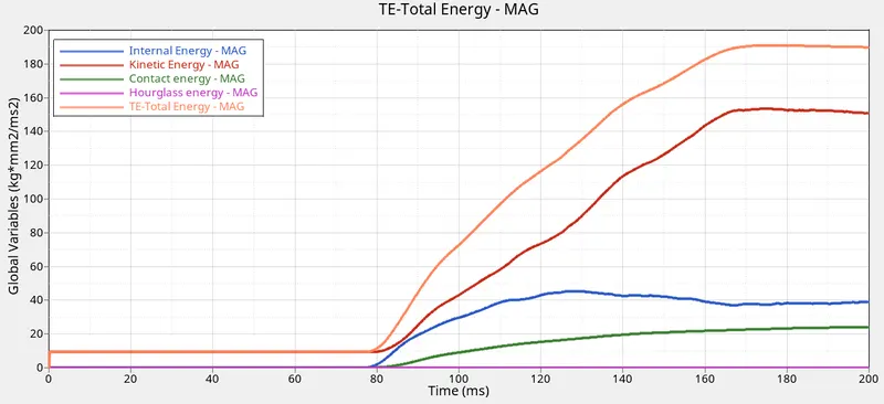
Energy vs Time
Since we have given imposed displacement to test plate the kinetic energy starts at the starting of simulation, but at 80ms only the test plate touches the roof, and deformation starts which makes the kinematic energy slowly increase and reaches a max at 153ms at 163KN/mm.
As a general rule, to determine whether an analysis is quasi-static, the kinetic energy of the deforming structure should not exceed a small fraction (typically 5%) of its internal energy throughout most of the simulation The internal energy in this simulation increases exponentially once the deformation starts at 80 ms and reaches max 45.4 at 129ms. The total energy should be equal to the external work done but this is simulation there is a slight loss in total energy that's because of contact energy.
However, the hourglass energy is kept minimal with the help of recommended elemental formulation
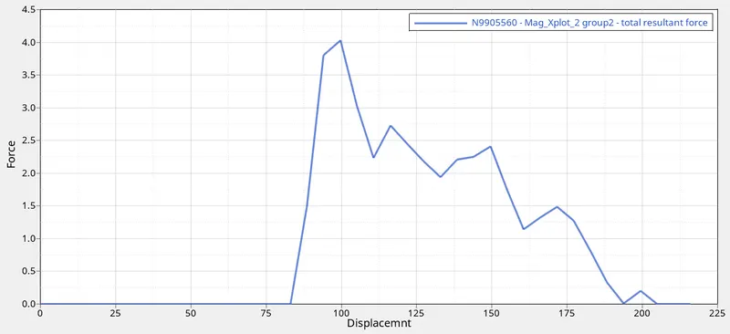
Force vs Displacement contour
Force vs displacement plot: We can see the a peak in the graph which occurs when the impactor hits the car. The total vehicle assembly is 175 kg = 1716 N. For the vehicle to pass the Roof crush test, it has to have the capability to withstand loads equal to 3 times its own weight, which in this case is 3 * 1716 = 5150.2 N or 5.15 kN. The peak force registered for the simulation is 4.197 kN which is below the calculated value. Thus the model has not passed the Roof crush test.
CONCLUSION:
1. The solver deck was successfully set-up for the Roof crush analysis as required.
2. The force vs displacement graph was plotted and a maximum force of 4.19 kN was noted.
3. The energy plots were also plotted for the simulation.
4. FMVSS 216, Roof Crush Resistance, establishes strength requirements for the passenger compartment roof of passenger cars, multipurpose passenger vehicles, trucks, and buses with a GVWR of 2722 kilograms or less.
The purpose of the standard is to reduce deaths and injuries due to the crushing of the roof into the passenger compartment in rollover accidents.