Comparison of crash tube results with default property simulation and improved shell element properties
OBJECTIVE:
Comparison of results with base simulation and improved shell element properties
1.In the crash beam file change the run time to 55 ms.
2. Change the number of animation steps during simulation to a minimum of 25 and maximum of 60.
3. Run the base simulation without any modification to element properties.
4. At the end of the simulation, do the energy error and mass error checks and determine whether the results would be acceptable.
5. If acceptable, Plot rigid wall forces, internal energy, hourglass energy, contact energy, total energy of the simulations.
6. Change all the shell elements properties to recommended properties, save this as separate, rad files and run the simulation.
7. Follow steps 5 and 6.
8. Create a brief report comparing all the results from steps 5 and 6 for both simulations.
9. Comment whether there is any change in the results and why there is any change in the result.
THEORY:
Altair RADIOSS is a multidisciplinary finite element solver developed by Altair.It is a fea solver mainly used for explicit analysis which uses various integration schemes to bring out solutions for engineering problems.
Hour glass is one of the most important parameter to avoid during analysis.It is a non-physical zero-energy mode which leads to excessive element distortions. The more structured and less distorted your elements are, the better the results. This does not happen in a real physical environment or experiments but takes place specifically in FEA simulation
The above is an example of a Single Integration point shell element. The values captured at the single integration point at the centre remains same as the dotted lines have not changed in magnitude or in angle. However, the element as a whole has shown a change in configuration. This is because elements with lesser integration points are less stiffer and as there is no stiffness in this mode, these elements have shown this kind of change in Configuration. Hour glass is not present in 3-nodeed tria elements or tetra elements
There are two methods to remove hour-glass
i.Viscous method/Perturbation method
- The hourglass deformation is detected with the relative motion of the nodes
- When hourglass is detected a force is applied on the node to stabilize the deformation. The force is defined according to the element stiffness
- The force introduces artificial energy(hor glass energy). The more the hourglass energy higher will be the chances of instability. This method is used in lshell=4(Q4)element formulation
ii. Physical Method/Stiffness Method
- In the physical/stiffness method the solver increases the stiffness of all the elements to avoid the occurrence of hourglass mod
- This is the most efficient method of hour glass removal
- The lshell=24 QEPH (preferred element shell formulation) uses this method to prevent hour-glassing.This shell elements formulation is the optimum for accuracy and cost
PROCEDURE:
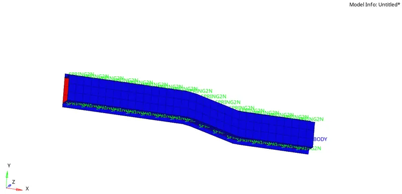
1.Open the given model in hypermesh Using Import-->Solver deck under radioss user profile
2.
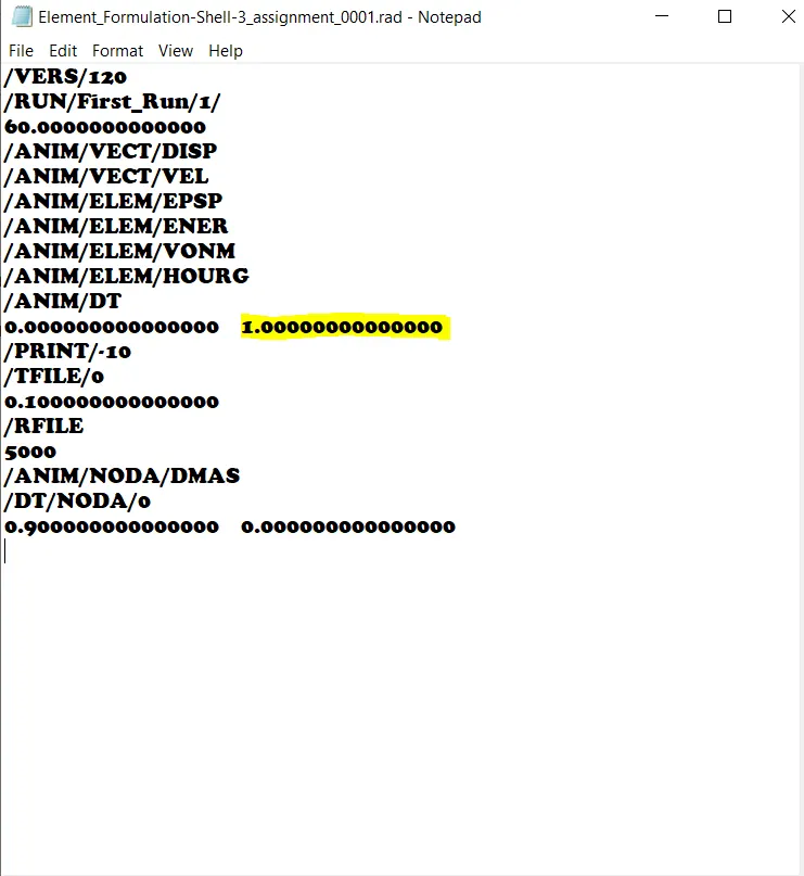
Change the run time to 55ms in the engine run card.This card will decide how long the simulation has to run
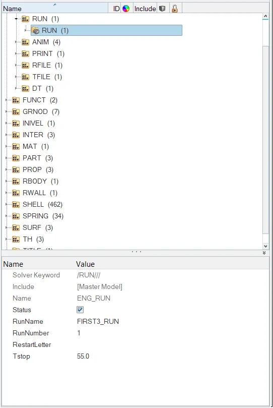
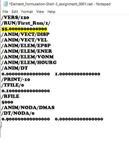
Engine Run Card Radioss Engine File
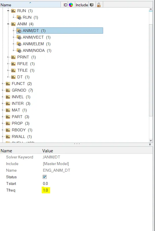
3.Then one of the other objectives was to change the number of animation steps to a number in between 25 and 60. The number of animation files generate will be decided by the time-frequency entered in the ENG_ANIM_DT card. Thus we edit the card value and keep it as 1 so we get 55 animations during the total run time
4.For our first simulation, the material properties are kept default. This can be checked by looking in the property cards
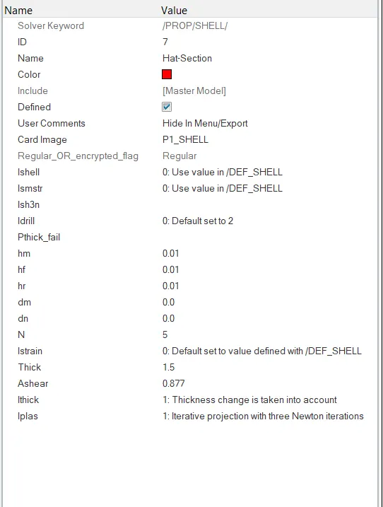
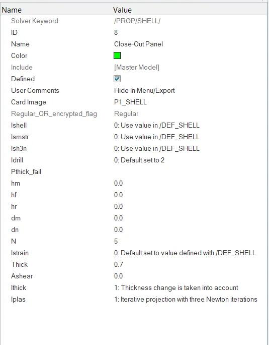
Property card-Hat Section Property card-Close Out Panel
5.Now for the initial simulation, we go to Analysis-->Radioss. We save the file by clicking save as and then save the file and set option to -nt 4 for faster computation

6.We then get the HyperWorks solver window popping out. On the completion of run , we can view the engine output file by clicking the output file option in the drop-down
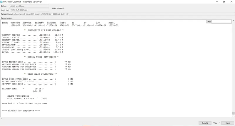
Opening the engine output file from the solver window
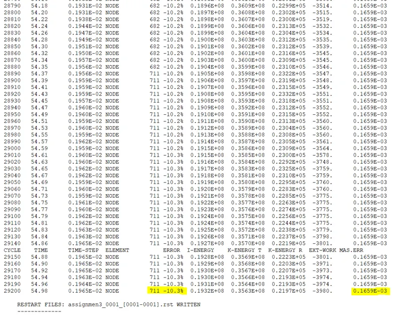
7.In the engine out file we have to check the mass errors and energy error are within the limit.The accepted values of energy errors are within 5 to -15% and mass error is 2-3%.In this case we can see that energy error generated is -10.3% which is acceptable and mass error is 0.016 which is also within the limit.
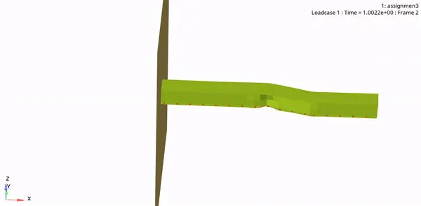
8.The simulation can be viewed in Hyperview(post-processor).The animation will be recorded based on the start time entered in the ENG_ANIM_DT card.This animation seems a bit unrealistic and hence is generally not acceptable
Rail crash simulation
Von-mises stress
9.Now let us generate the necessary plots.Open a new page and switch to Hypergraph 2D,Load the time history which would be a T01 file
Time vs IE_KE_CE_HG3_TE
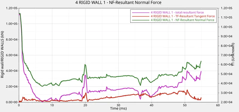
Time vs Rigid wall forces
II.Now we move on to the simulation with next set of property cards
Repeat the procedures 1-3
4. The below are the prescribed properties for our next simulation
|
Parameters |
Comment | |
|
Ishell =24 |
QEPH 4 nodes shells are best combination of cost and accuracy. | |
|
Ismstr=2 |
Full geometric nonlinearities (default)with possible small strain formulation activation in RADIOSS Engine. | |
|
Ish3n=2 |
Standard 3 noded shell (C0)with modification for large rotation(default) |
|
| N=5 | Number of integration points set to 5 for accuracy bending. | |
|
Ithick=1 |
Thickness change is taken into account for accuracy. |
|
|
Iplas=1 |
Iterative plasticity for good accuracy. |
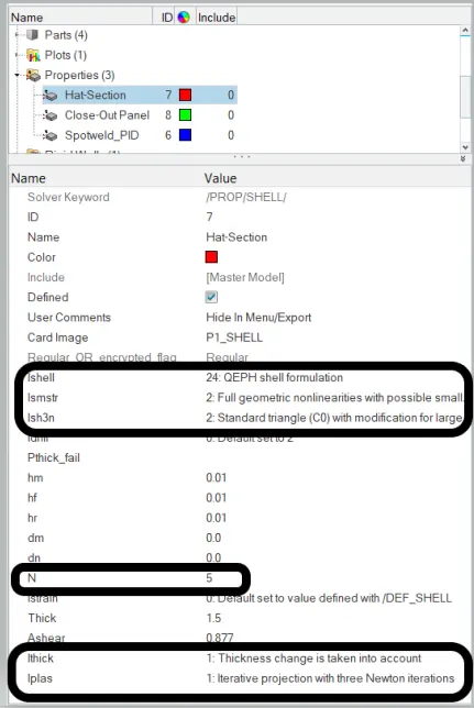
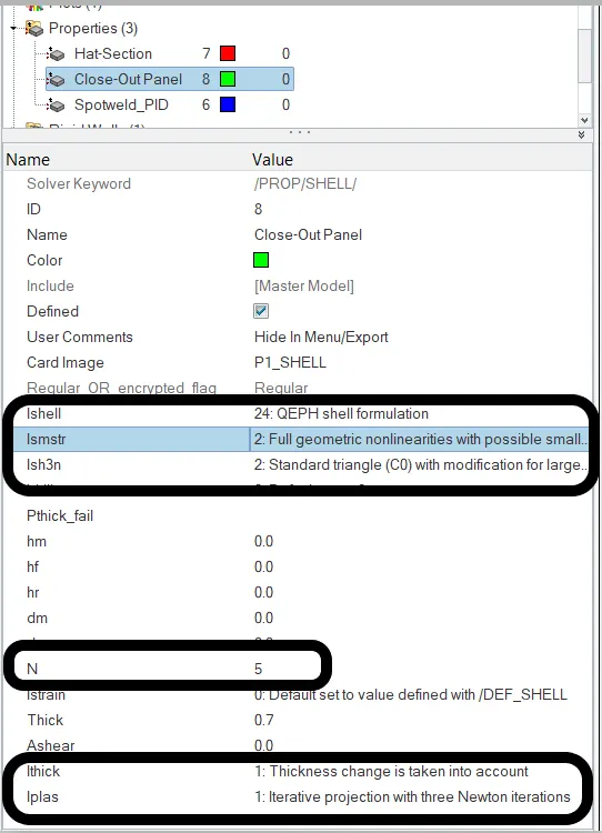
5.Repeat procedures 5-7 from the previous simulation steps. We get our new resuts
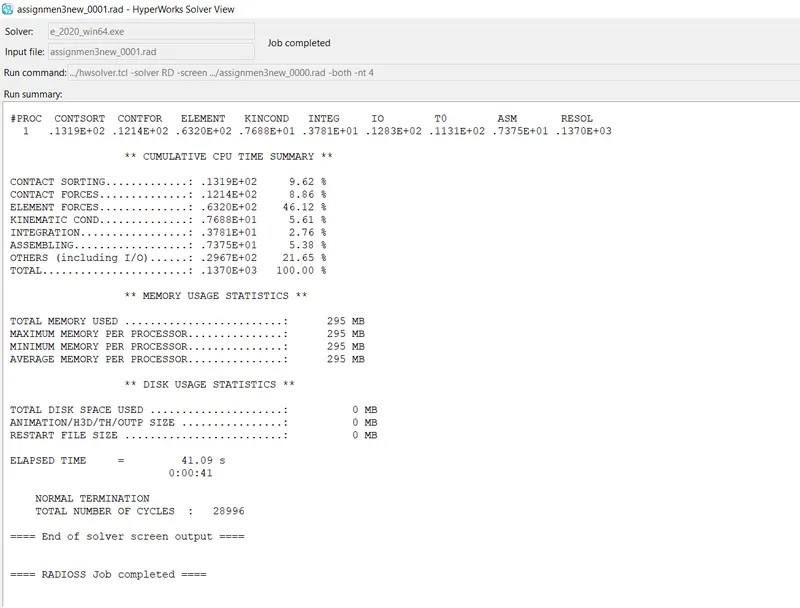
6.In the engine out file we have to check the mass errors and energy error are within the limit.The accepted values of energy errors are within 5 to -15% and mass error is 2-3%.In this case we can see that energy error generated is -0.1% which is acceptable and mass error is 0.016 which is also within the limit. Hence we move further to plot various data
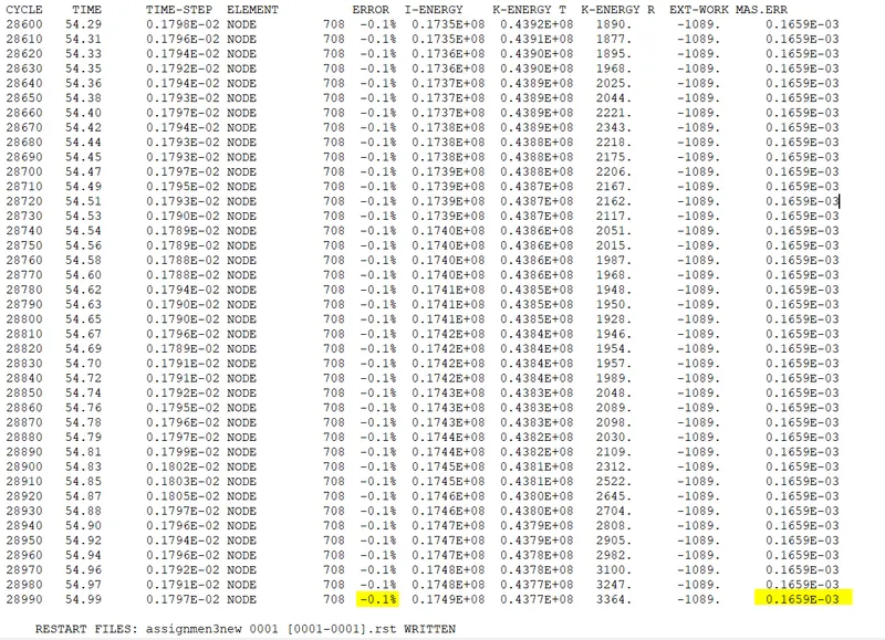
The energy has changed here to 0.1% due to a better element formulation
7.The animation can be viewed in Hyperview post-processor. We will further analyze the result by analyzing the plots and various contours
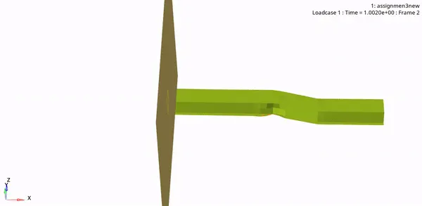
Rail crash simulation
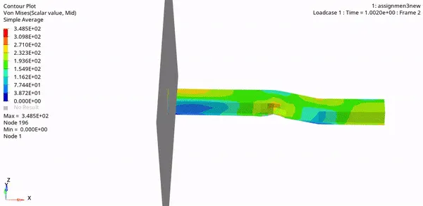
Von-mises Stress
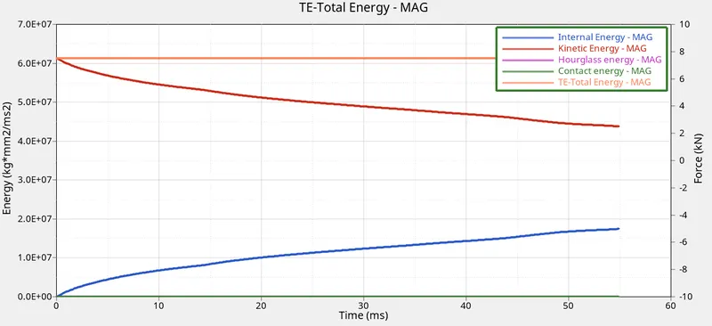
Time vs IE_KE_CE_HG3_TE
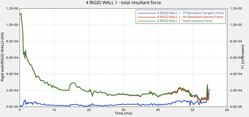
Time vs Rigid wall forces
8. Now all our required plots have been generated for both cases
RESULTS:
Crash tube animation:
CASE I: CASE II:
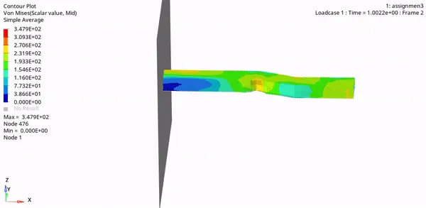
Here we can clearly observe that case2 is more preferable/realistic as it has its end part not deformed until intact whereas in case 1 there is extensive deformation at the end even when not in impact
The reason for this unrealistic deformation in case 1 would be due to hourglass which in the second case was successfully prevented using lsell=24
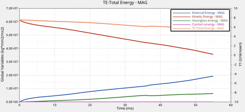
Here comparing both plots we can see the hourglass energy reduced to zero in case2 due to the usage of QEPH element formulation
Also we could observe a decrease in total energy in case 1 which is generally not acceptable.The elimination of hourglass energy helped to get a nearly constant curve for T.E in case 2
Here in case 1 the TE is touching the zero line at nearly 6ms which is highly unrealistic which is avoided in case 2 with the use of preferred shell formulation
CONCLUSION:
- The use of recommended shell properties has resulted in much more acceptable results
- Energy error decreases from -10.3% to -0.1%
- The hour glass gets reduced to zero using preferred shell properties in the second case