Modelling of shell elements in hypermesh
AIM:
Mesh the following component and assign the corresponding thickness:
| S.N | Quality Criteria | Value |
| 1 | Min Length | 3.5 |
| 2 | Target | 5 |
| 3 | Max Length | 7 |
THEORY:
PROCEDURE:
Import the given model to hypermesh. We can select RADIOSS as our user profile
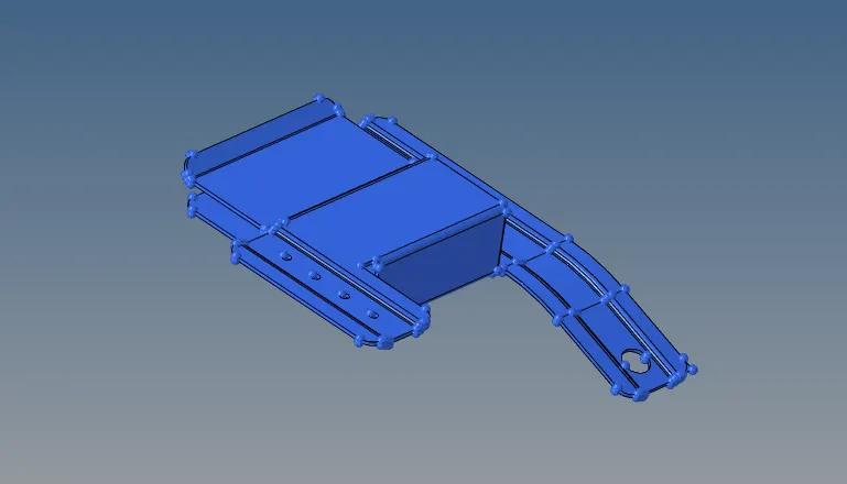
Our next step is geometry clean up.When we change the mode to Topo mode we can see many free edges which has to be cleaned up. For this, we can use the toggle option and fill surface
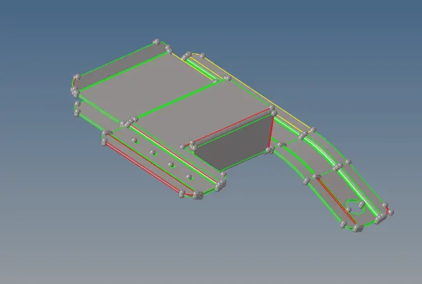
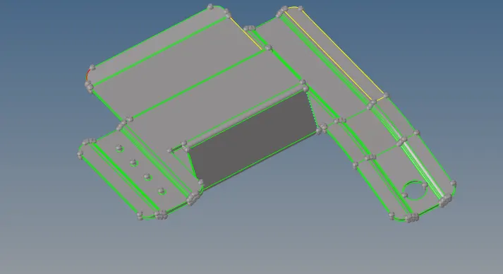
We have corrected all free edges part , now some yellow lines is visible indicating of a intersected edge i.e more than 1 surface is present hence there are presence of duplicate surfaces.Deleting the duplicate surfaces help us avoiding all those intersection edges. Hence we get a completely clean object
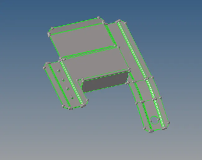
Next we extract the mid surface using the auto-mid surface-skin option.All holes below 6mm diameter can be ignored for crash analysis. Hence we fill those small holes having an approximate diameter of 2mm
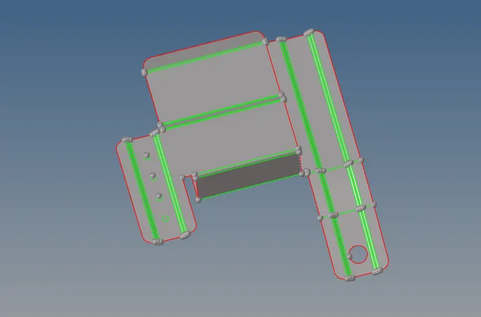
We can find small fillet regions that will fail below our min length quality criteria. Those can be captured using a mid line using Geom->lines->midline option or can be defeatured using the grom-defeature command
In the end parts we see many small fillets which
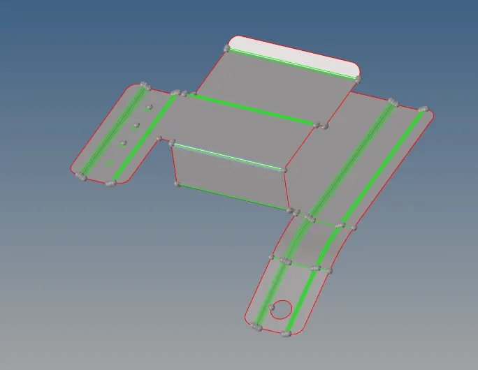
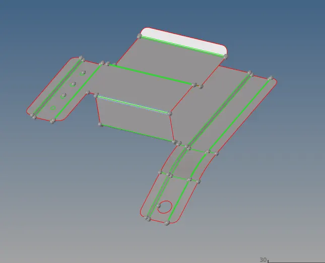
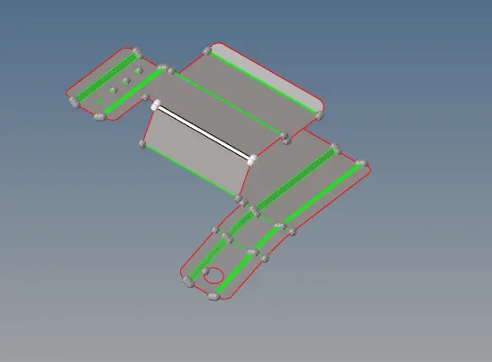
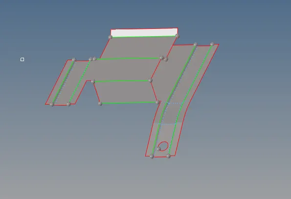
We then mesh this component using the 2D->automesh panel. We set the target element length as 5mm and use mixed type as the element type
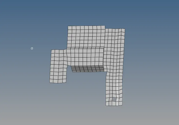
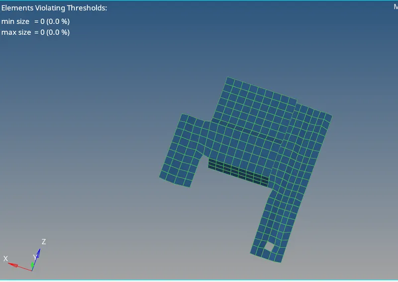
We then check the quality of the element using F10 check elements panel or 2d->qualityindex. W ith this we assure that there are zero elements failing for the given quality criteria.
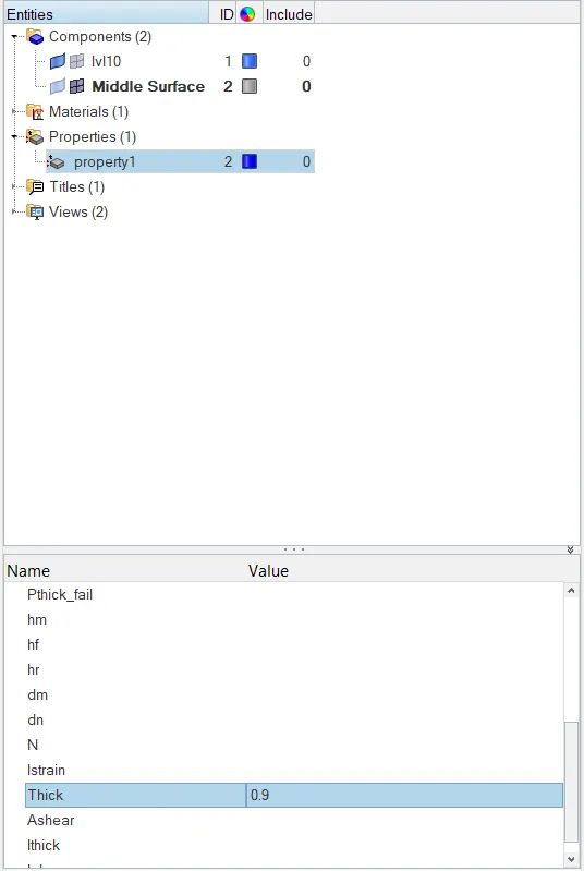
Now after we have meshed we have to assign the respective thickness assigning the respective property by creating a new property with the respective thickness. Then to view with thickness we select the option 2d element representation
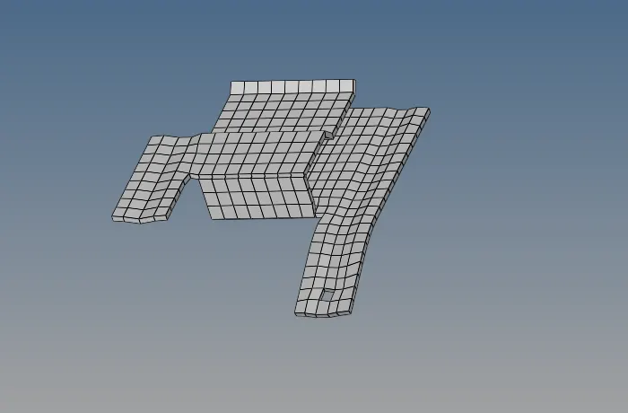
We then check for proper connectivity using the Shift+F3 option. We see no free edge in between components hence proper connectivity is ensured
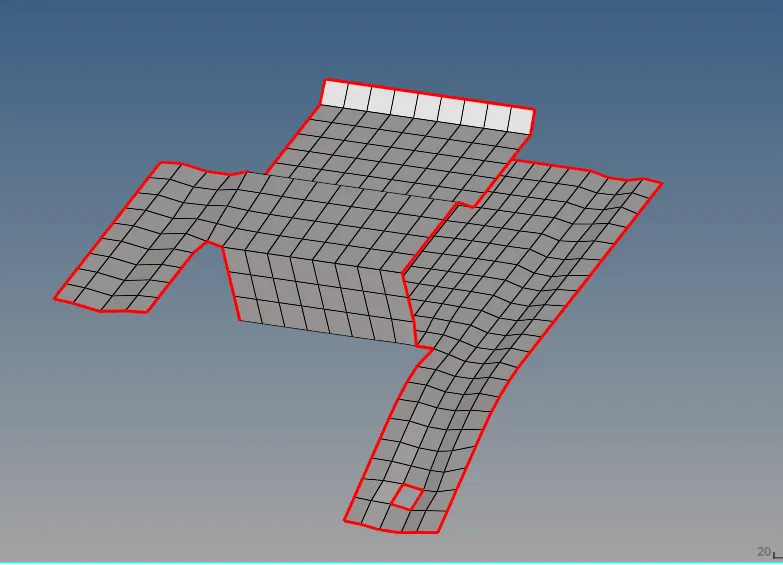
Part II:
Import the given model into hypermesh
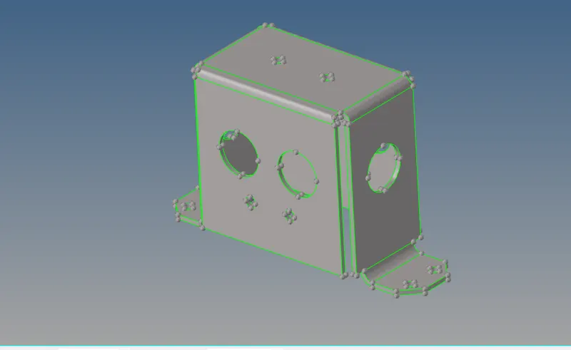
Our next step is geometry clean up.When we change the mode to Topo mode we can see many free edges which has to be cleaned up. For this, we can use the toggle option
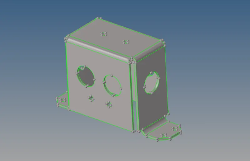
Now we extract the mid surface using the auto midsurface -skin option
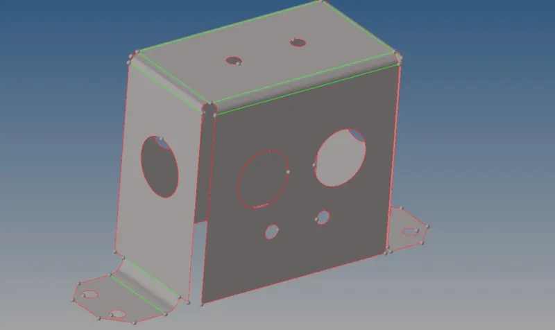
We fill all holes below 5mm and assign washer splits if possible to other large holes for well capturing of holes
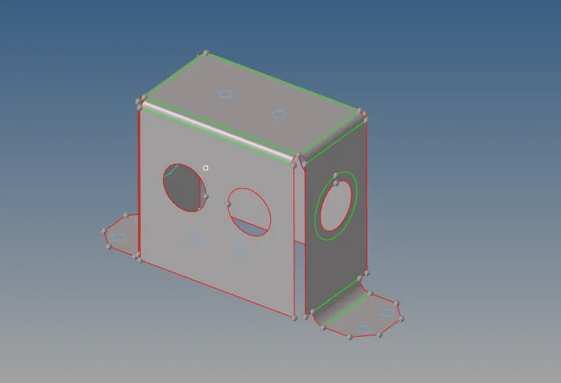
The mid surface generated is assigned respective thickness by assigning their properties. The quality criteria was defined in the criteria file settings. We then mesh the given component . Our main aim is to ensure there isnt any trias/minimal in number and there shouldnt be any rotating quads
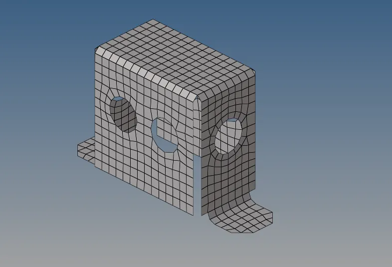
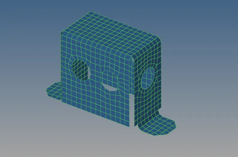
We then check for proper connectivity using the Shift+F3 option. We see no free edge in between components hence proper connectivity is ensured
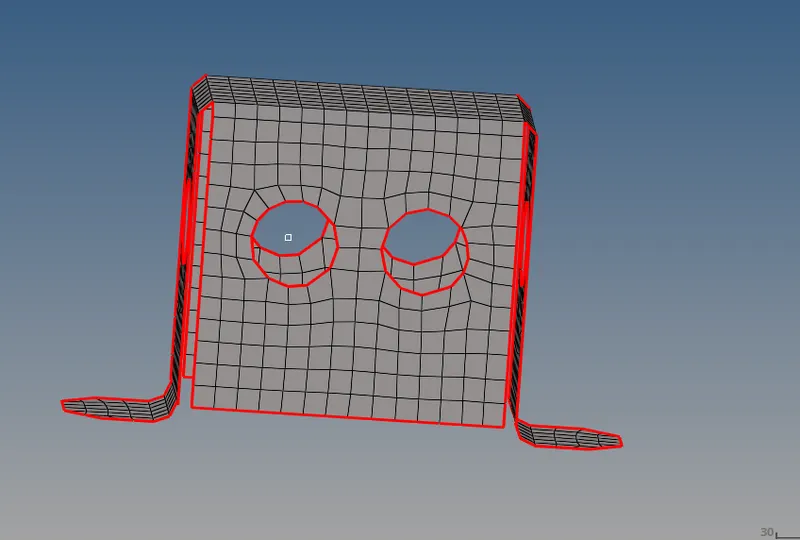
Part III:
Import the given model into hypermesh
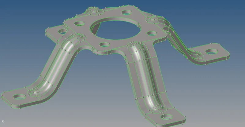
Check for any topological errors.The imported geometry did not have any free edges
The mid surface is generated using the auto mid surface panel in geometry. The mid surface generated is defeatured in some areas and certain lines are toggled for a proper mesh flow. We assign respective thickness to the mid-surface
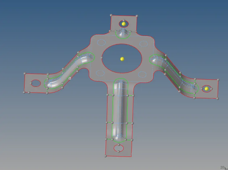
The component is next meshed.The quality criteria was defined in the criteria file settings. We then mesh the given component and verify our quality criteria using the check elements panel/quality index in 2d
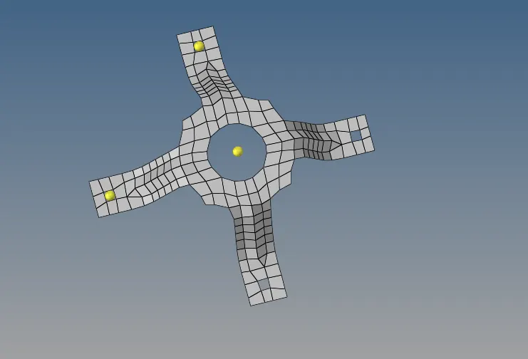
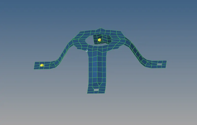
We then check for proper connectivity using the Shift+F3 option. We see no free edge in between components hence proper connectivity is ensured
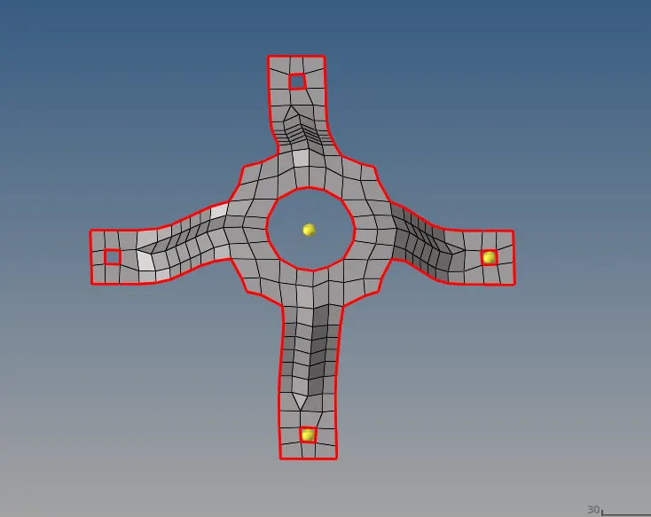
RESULTS:
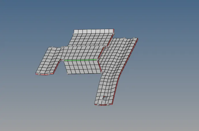
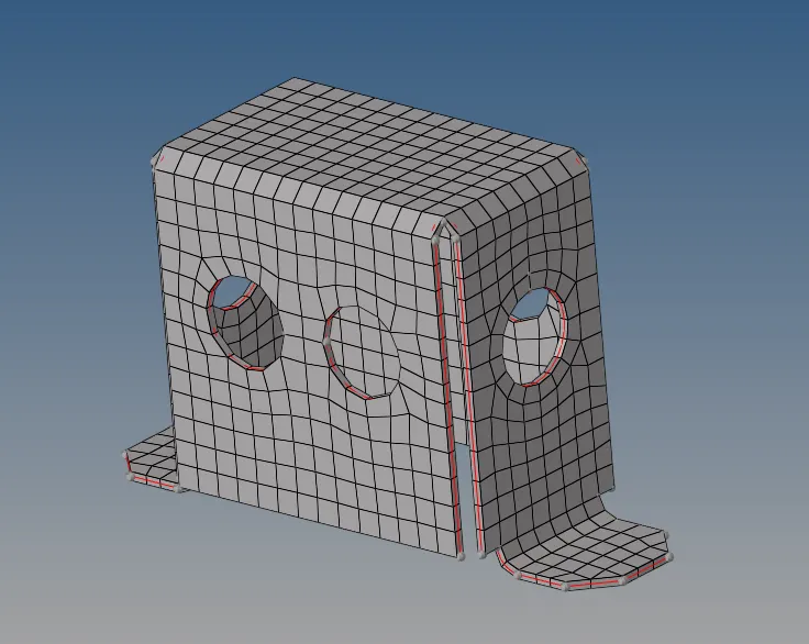
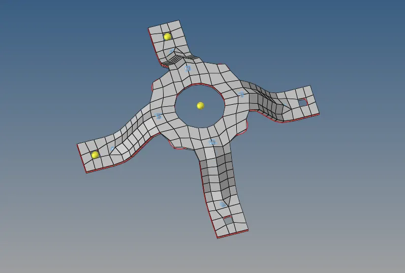
The following components were meshed and respective thickness were assigned
All the off elements were cleared and perfect quality was achieved