Sheet metal Bending challenge
SHEET METAL BENDING
OBJECTIVES:
In these challenges, Sheet metal bending is to be performed for 3 different materials mentioned below. Variation of certain settings is also to be performed and your conclusions are to be added to the report Run the analysis for the material:
Case 1:Aluminium Alloy 1199( mentioned in the course video),Copper Alloy NL and Magnesium Alloy NL. Find out the Equivalent stress, Equivalent elastic strain and Total Deformation in Y direction and compare the results for the three materials.
Case 2:With the material as Aluminium Alloy, change the friction coefficient to 0.19 and run the analysis as mentioned in Case 1. Compare the results with that in case 1.
Case 3: Refine the mesh on the plate such that it doesn't cross the academic limit. With Aluminium alloy as material, run the analysis as in Case 1 and compare the results.
THEORY:
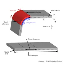
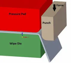
Bending is a metal forming process in which a force is applied to a piece of sheet metal, causing it to bend at an angle and form the desired shape. A bending operation causes deformation along one axis, but a sequence of several different operations can be performed to create a complex part.
PROCEDURE
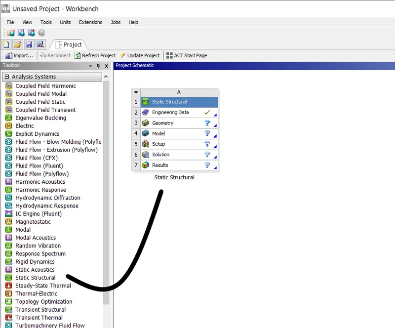
1. First, we open Ansys Workbench and import static structural module.Then we have to input the engineering materials with required properties or else by creating with required properties.
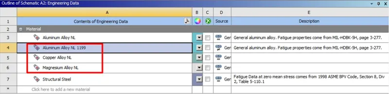
2. Now we open engineering data and add the required material for the simulation. We add the required materials and set its respective properties in the engineering data tab and procced for the geometric visualisation
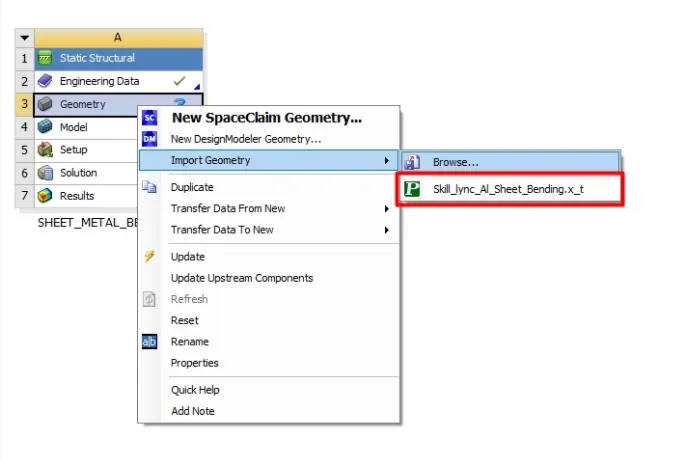
3. Then we import our model into ANSYS and open it in SpaceClaim to visualise the object. This is very key as we check the model for any defects or damages and move ahead for the simulation
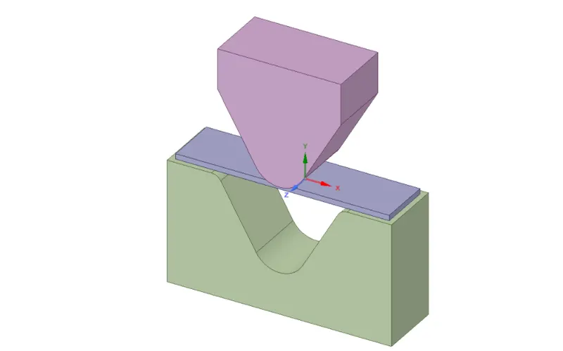
SHEET METAL BENDING GEOMETRY
4. Now we have to set the contacts for the body. Contact is said to occur when the surfaces of two separate objects touch each other such that the surfaces are mutually tangent to each other. The surfaces in contact do not interpenetrate and can transmit forces from one body to the other. In order to prevent the interpenetration between the surfaces, the ANSYS program or any FEA software has to establish relations between the surfaces and this is done using CONTACT FORMULATIONS. The following contacts were set for the analysis
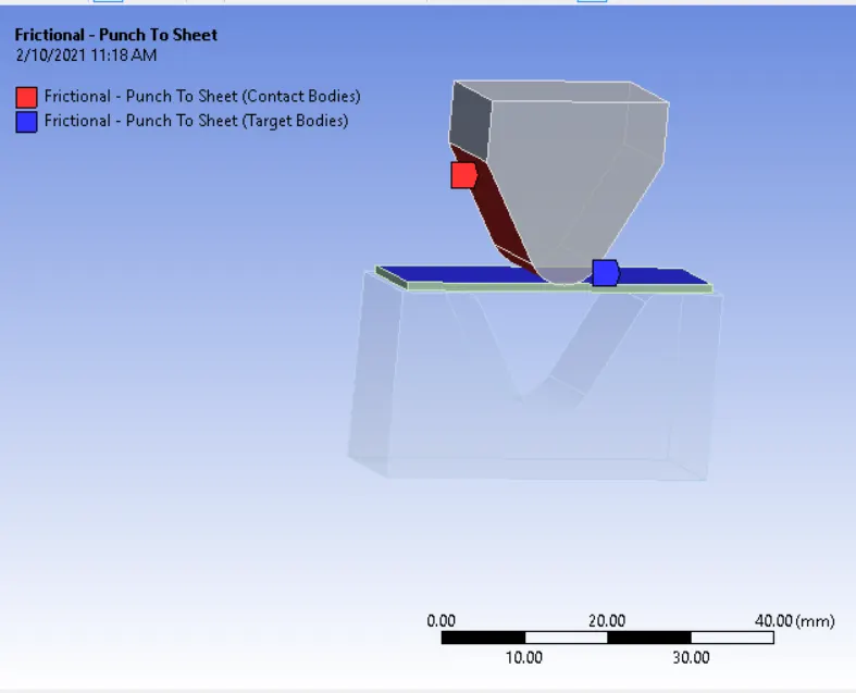
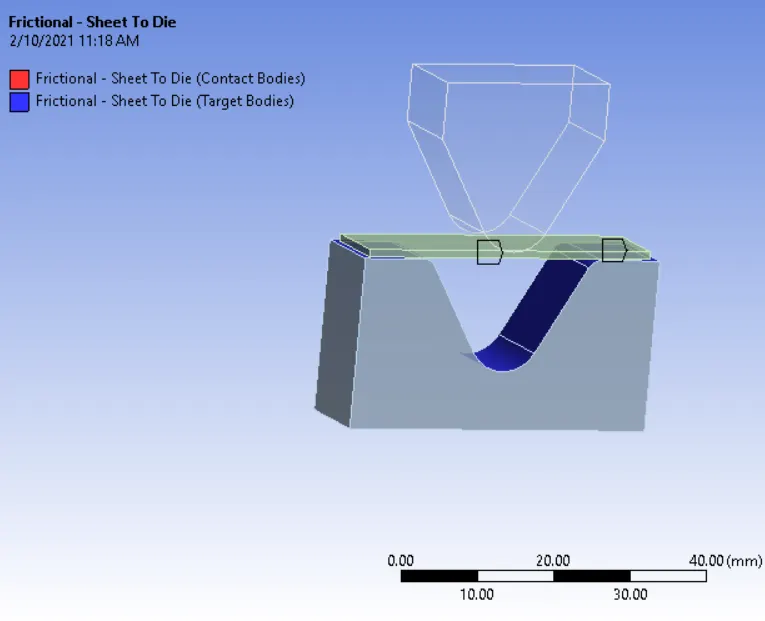
CONTACT DEFINITIONS
After setting up the contact now we have to proceed to meshing. A Mesh is a network that is formed of cells and points. Meshing is a part of the engineering simulation manner where complex geometries and models are divided into simple elements that can be used as discrete local approximations of the larger domain
We insert face sizing mesh in various regions of contact for more accurate results. We use of a mesh of 4mm and a face sizing of 1mm at the regions of interest
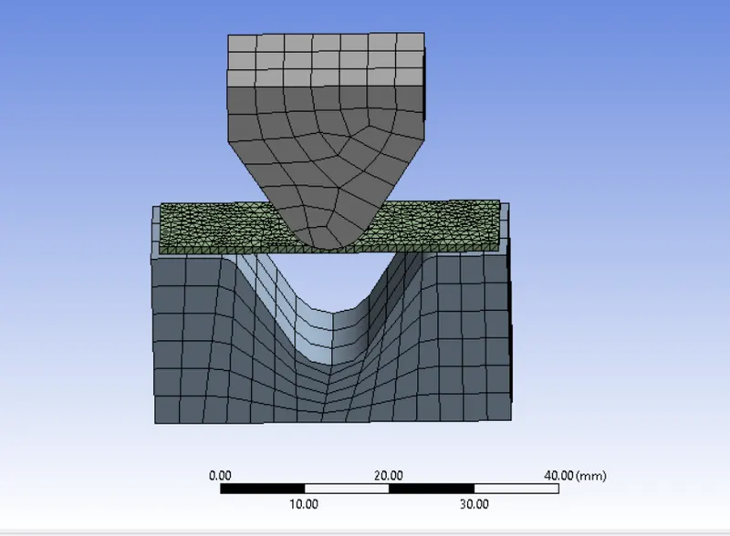
MESHED MODEL
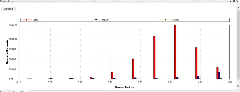
MESH METRICS
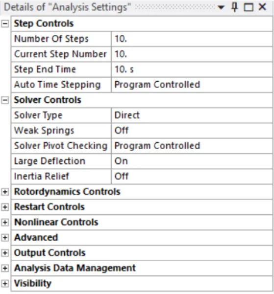
Now we have to set up the analysis parameters. We also set up the displacements and fixed loads for the punch and sheet
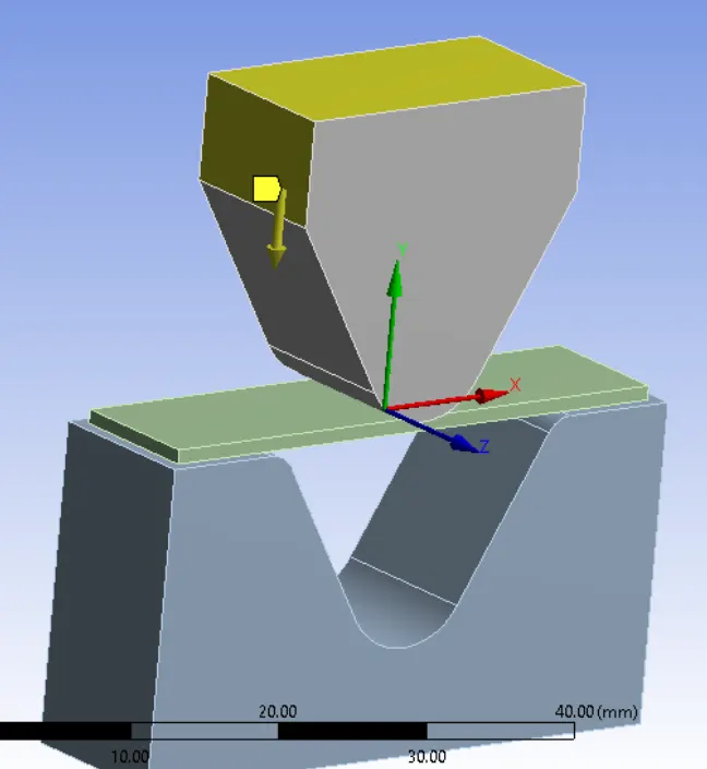
Displacement applied on the puch
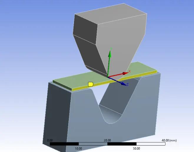
Displacement of sheet in z-direction
RESULTS
ALUMINIUM ALLOY
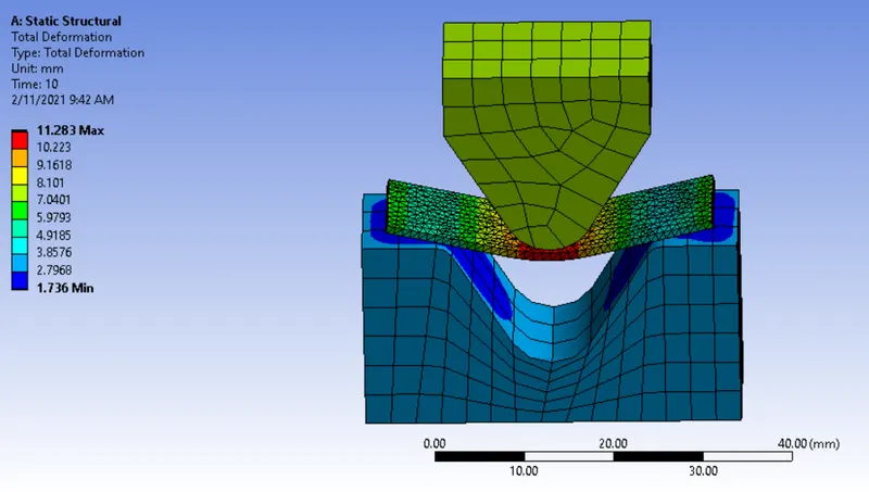
TOTAL DEFORMATION
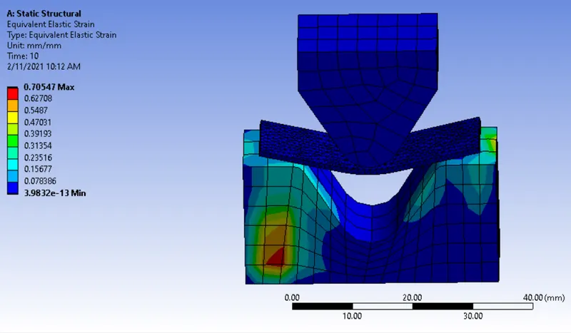
EQUIVALENT ELASTIC STRAIN
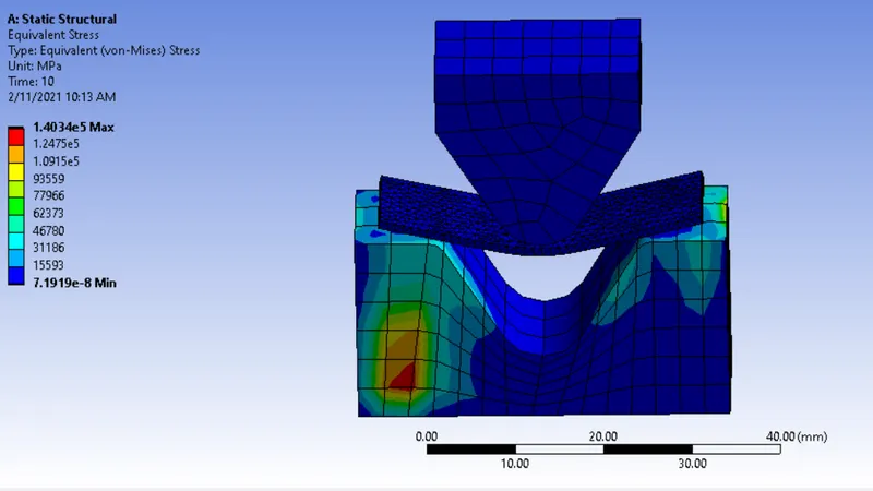
VON MISES STRESS
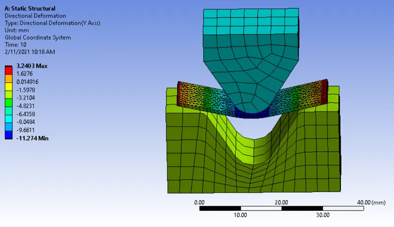
Y-DIRECTIONAL DEFORMATION
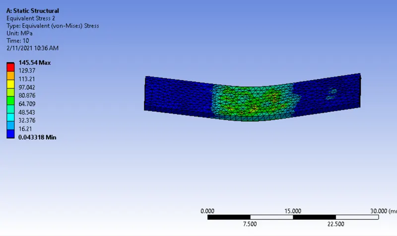
EQUIVALENT STRESS ON SHEET
COPPER ALLOY NL
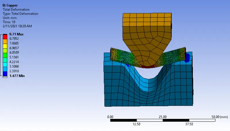
TOTAL DEFORMATION
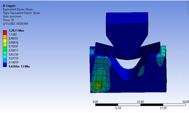
EQUIVALENT ELASTIC STRAIN
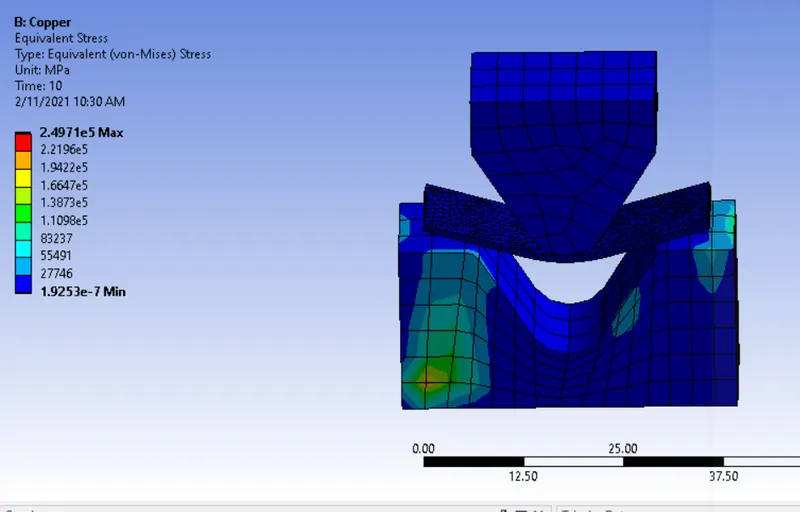
VON MISES STRESS
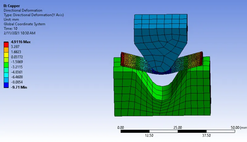
DIRECTIONAL DEFORMATION
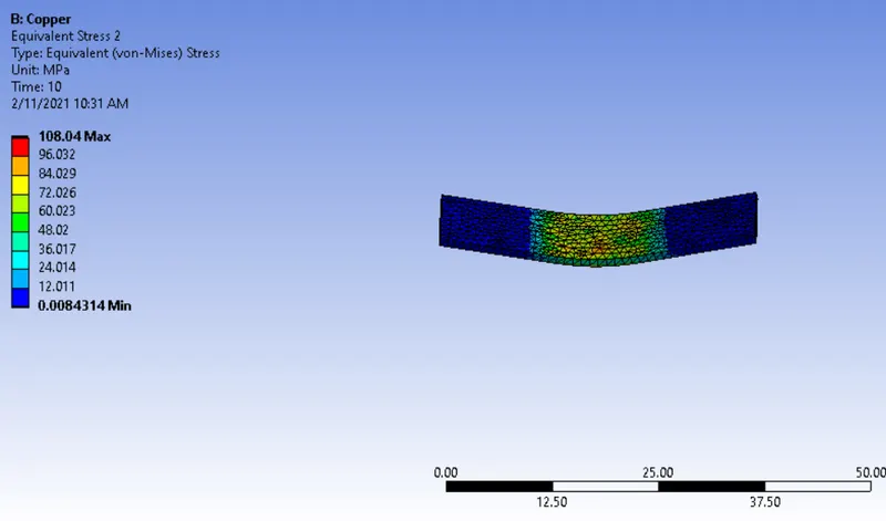
VON MISES STRESS ON SHEET
MAGNESIUM ALLOY
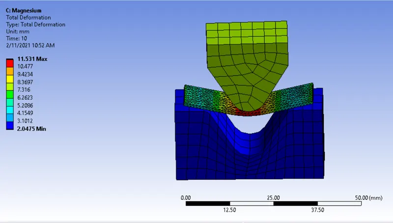
TOTAL DEFORMATION
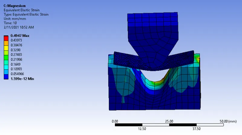
EQUIVALENT ELASTIC STRAIN
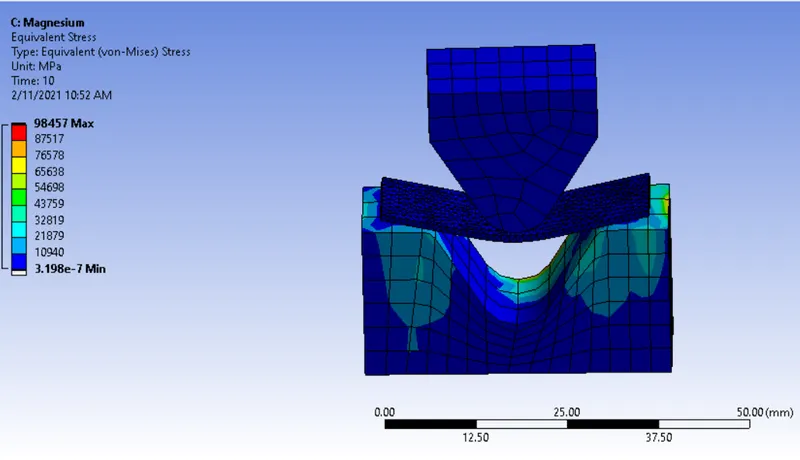
VON MISES STRESS
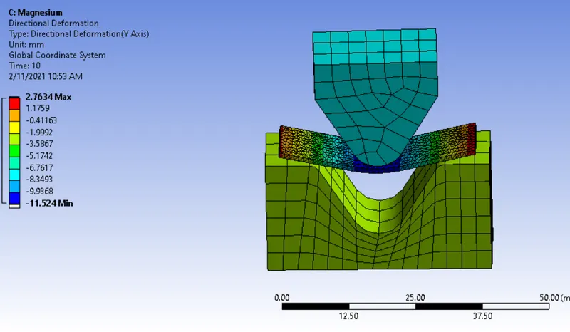
Y DIRECTION DEFORMATION
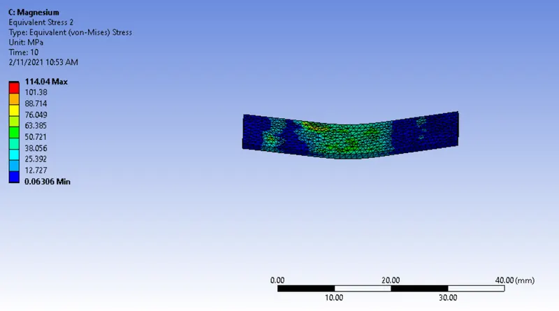
VON MISES STRESS IN THE PLATE
| VON MISES STRESS ON PLATE | EQUIVALENT STRAIN | AXIAL DEFORMATION | |
| ALUMINIUM | 145.54 | 0.705 | 3.2403 |
| COPPER | 108.04 | 1.2671 | 4.911 |
| MAGNESIUM | 114.04 | 0.494 | 2.7634 |
- ALUMINIUM PLATE experience the most stress on it where copper has the highest equivalent strain and directional deformation
- Also copper being the most ductile it experiences the highest von-mises stress
CASE 2
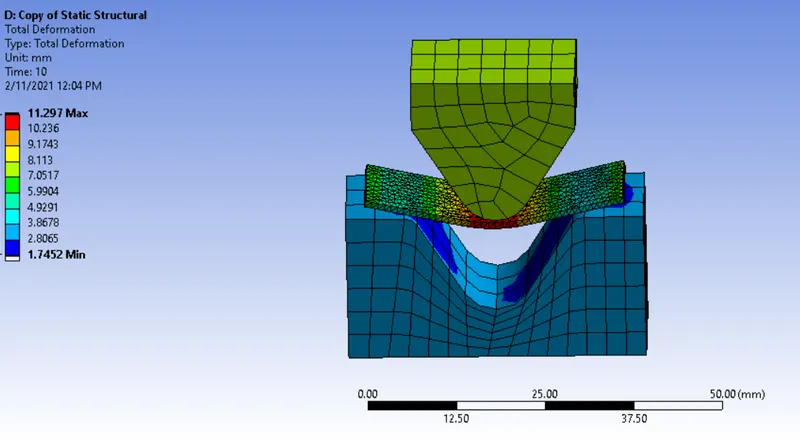
TOTAL DEFORMATION
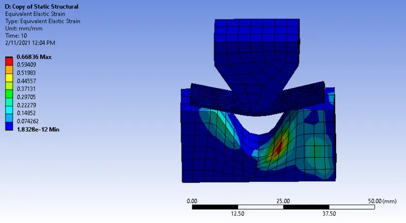
EQUIVALENT ELASTIC STRAIN
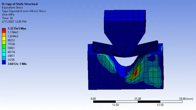
VON MISES STRESS
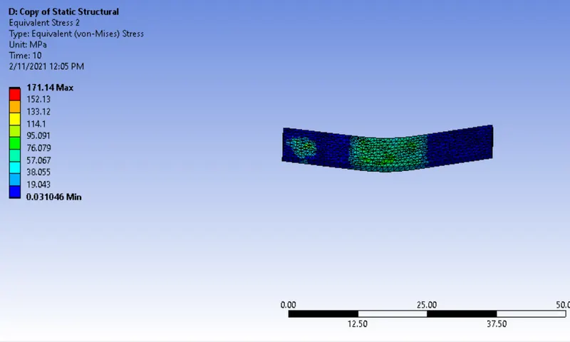
VON MISES STRESS ON THE SHEET
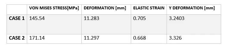
We see an increase in values such as von mises stress, deformation but a marginal decrease in elastic strain too can be found as we increase the frictional coefficient
CASE 3:
Now we refine the mesh and update it to a size of 1.8 mm where we end up with 26k nodes which is the best mesh we can get for this model within the academic version
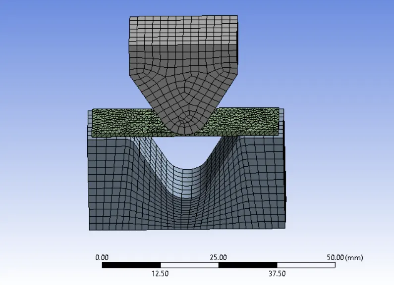
MESHED MODEL
One of the major difference observed was the computational time which was 10 minutes in case 1 compared to 140 minutes in case 2
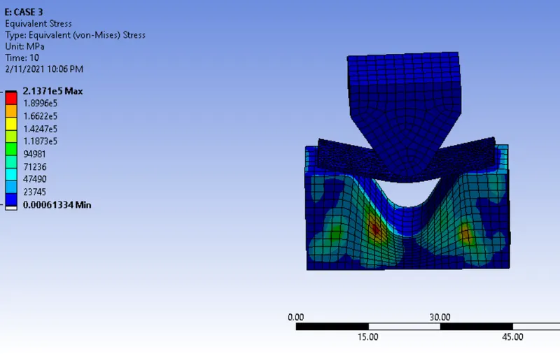
1.9mm MESH MODEL 4mm Meshed model
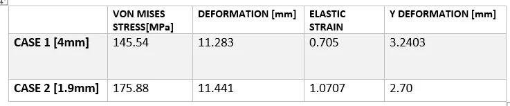
We can observe some significant changes in the values as we refine the mesh but it also takes a higer computational time
CONCLUSION:
The test cases were set up and run successfully
In case 1 copper being the most ductile, it experiences the highest von-mises stress
In case 2 we see an increase in values such as deformation, stress but a slight decrease in strain can be observed as we increase the friction coefficient
From the above results we see as we refine the mesh we get more accurate results, but computational time increase
The simulation files are attached here