Verification of Weld Joints
AIM:
Simulate three different types of welding using three different weld materials
THEORY:
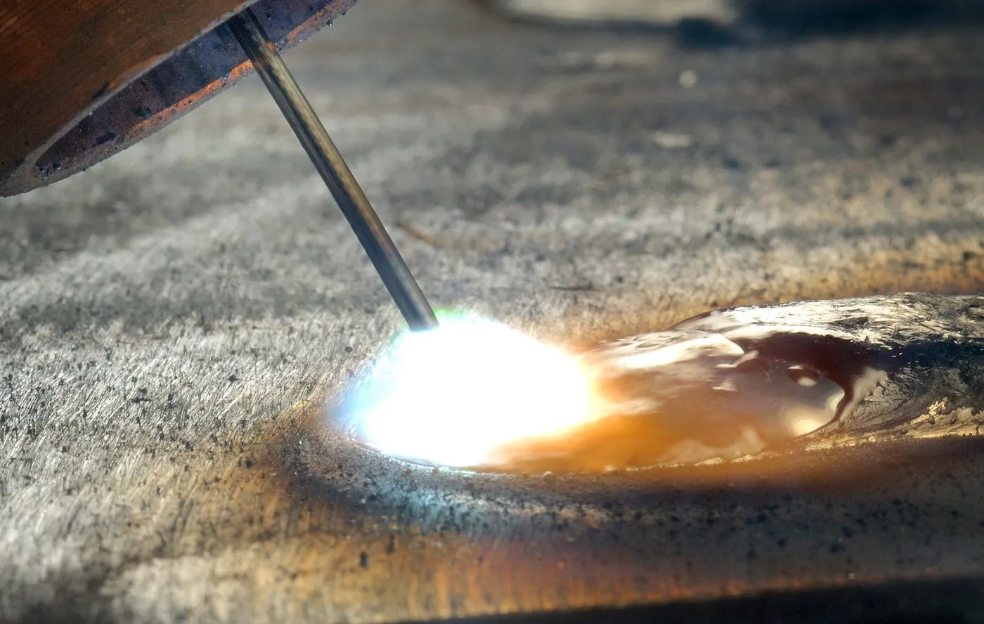
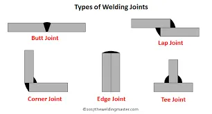
Welding is a fabrication process whereby two or more parts are fused together by means of heat, pressure or both forming a join as the parts cool. Welding is usually used on metals and thermoplastics but can also be used on wood. The completed welded joint may be referred to as a weldment
A brazed joint is made in a completely different manner from a welded joint. The first big difference is in temperature – brazing does not melt the base metals. Brazing temperatures are also significantly lower than welding temperatures for the same base metals, using less energy.
MATERIALS USED :
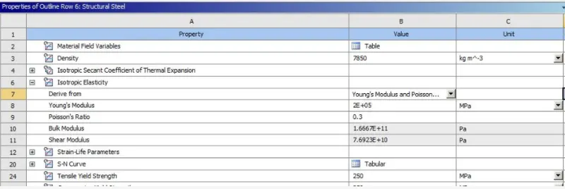
STRUCTURAL STEEL
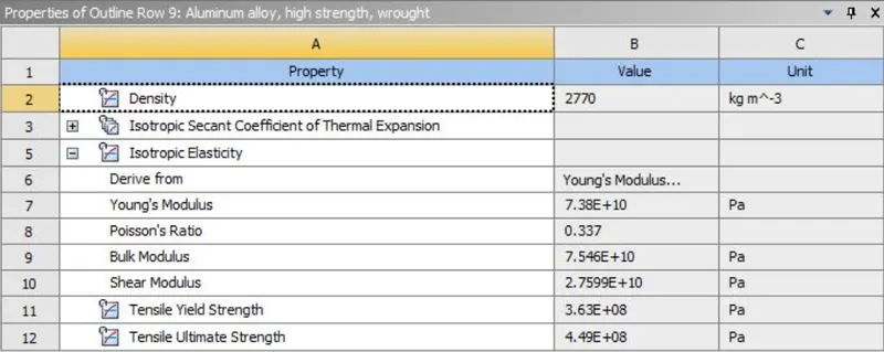
ALUMINIUM ALLOY
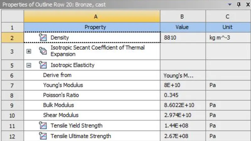
BRONZE
PROCEDURE:
Open Ansys workbench and import static structural analysis
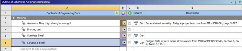
Open engineering data and add the required materials
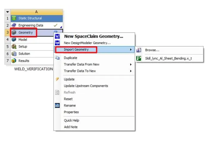
Now we click on geometry and select import geometry
We can check whether the imported geometry is proper or not in SpaceClaim. Through our visual inspection, it can be confirmed it has no defects and we proceed further for the simulation
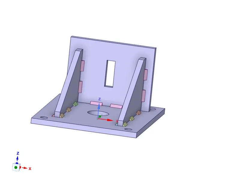
GEOMETRY OPENED IN SPACECLAIM
Open ansys mechanical module for meshing and analysis setup. We can also rename certain parts for easy identification
We have to run three different cases differing the material. Here in case 1 we are using structural steel
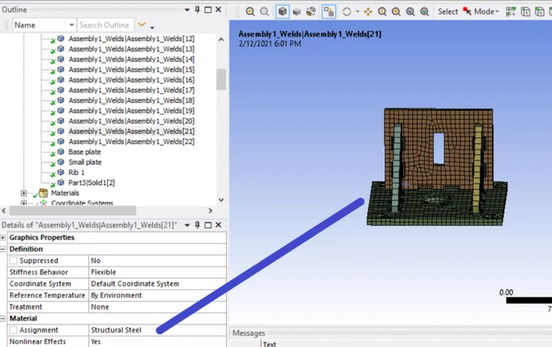
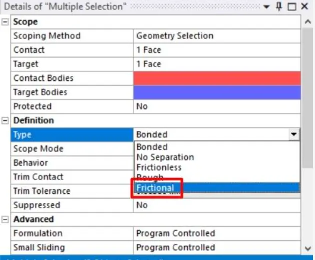
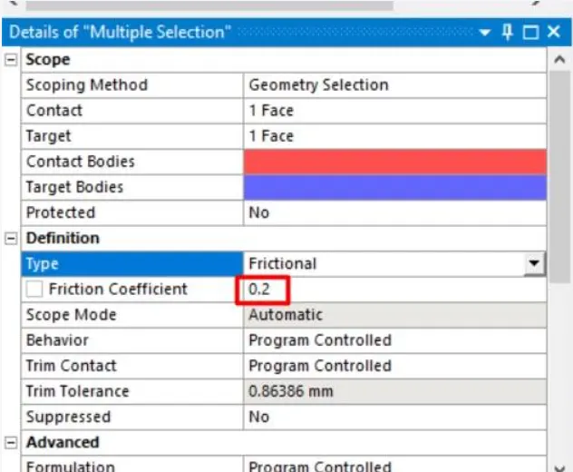
We change these pre defined contacts to frictional contacts and assign a frictional coefficient of 0.2
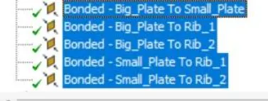
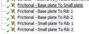
CONTACTS DEFINITION
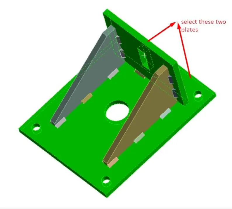
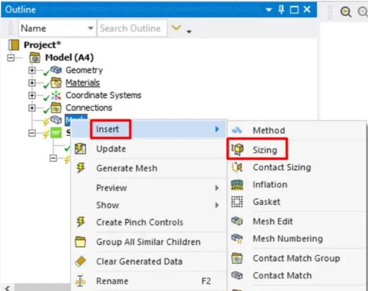
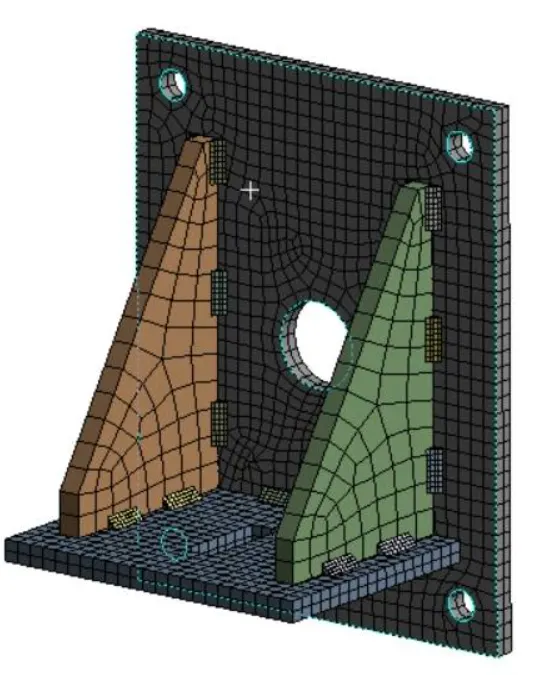
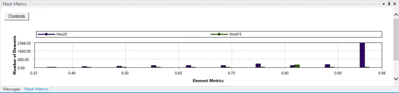
Now we go to mesh tab and assign a face sizing on the plates of 7mm and generate mesh on the component
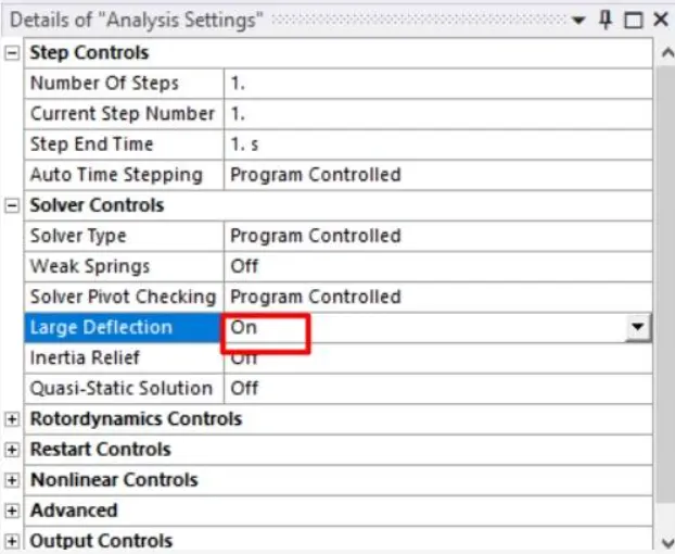
Now we move on to analysis settings and give a time step of 1 and also we turn on large deflections to consider those
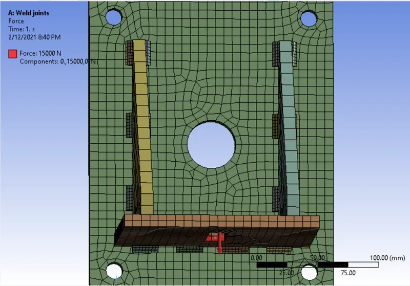
Then we apply the constraints and load on onto the component. The 4 small circular holes are given fixed support and the rectangular plate is given a force of 15000N in the Y-axis
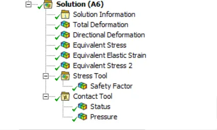
Now we add the required outputs in the solution block and proceed with the simulation
RESULTS:
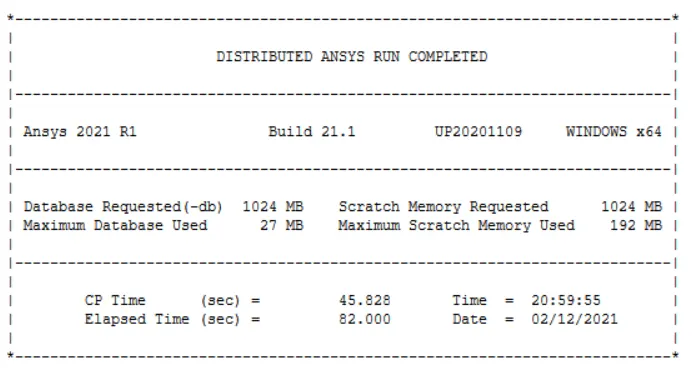
As we have just set 1-time step the solution converges quickly and we can view the solver output details in solution block
After we run the simulation we can turn on the Max and Min probe to view the location of max and min of respective properties
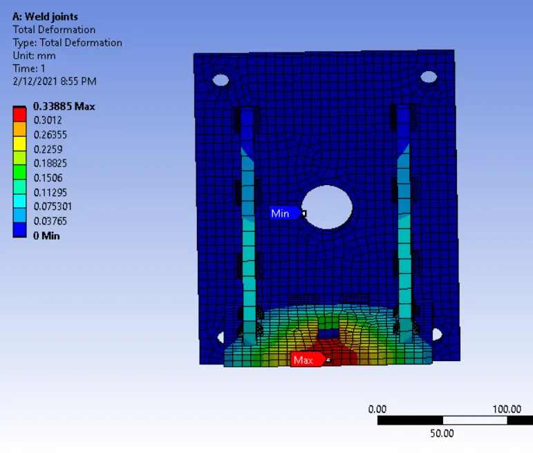
TOTAL DEFORMATION
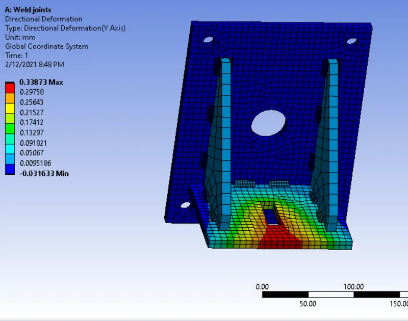
DIRECTIONAL DEFORMATION
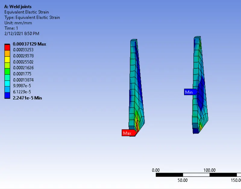
EQUIVALENT STRAIN ON RIBS
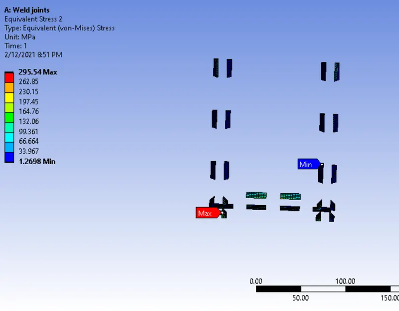
EQUIVALENT STRESS ON WELD JOINTS
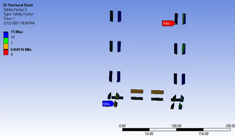
SAFETY FACTOR
Here we can see those having safety factor less than 1 would fail and more than 1 are safe
CASE II: Here the material to be chosen for this case is Aluminium alloy(high strength, wrought). [Plate material to be used is stainless steel]
We repeat the same procedures as mentioned for case 1 with different material
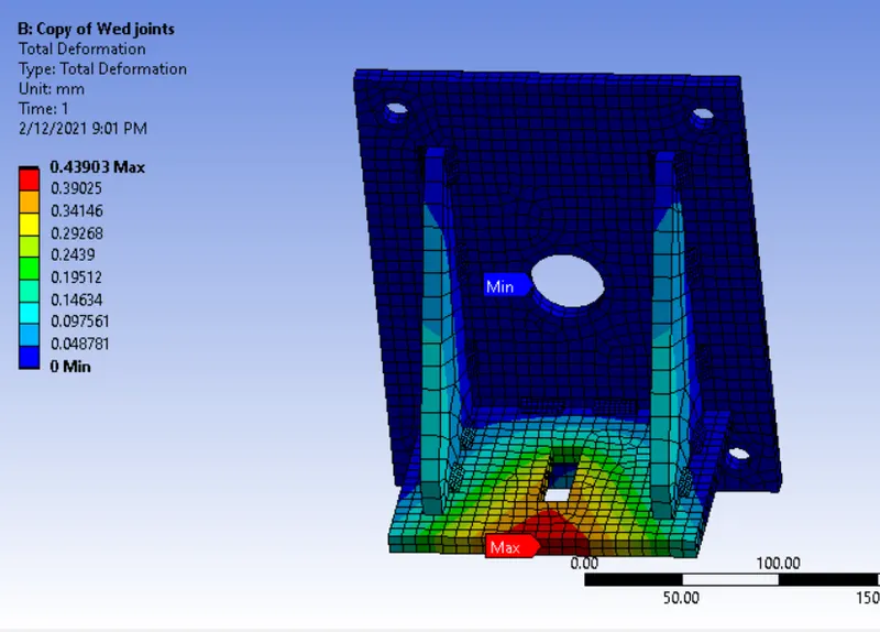
TOTAL DEFORMATION
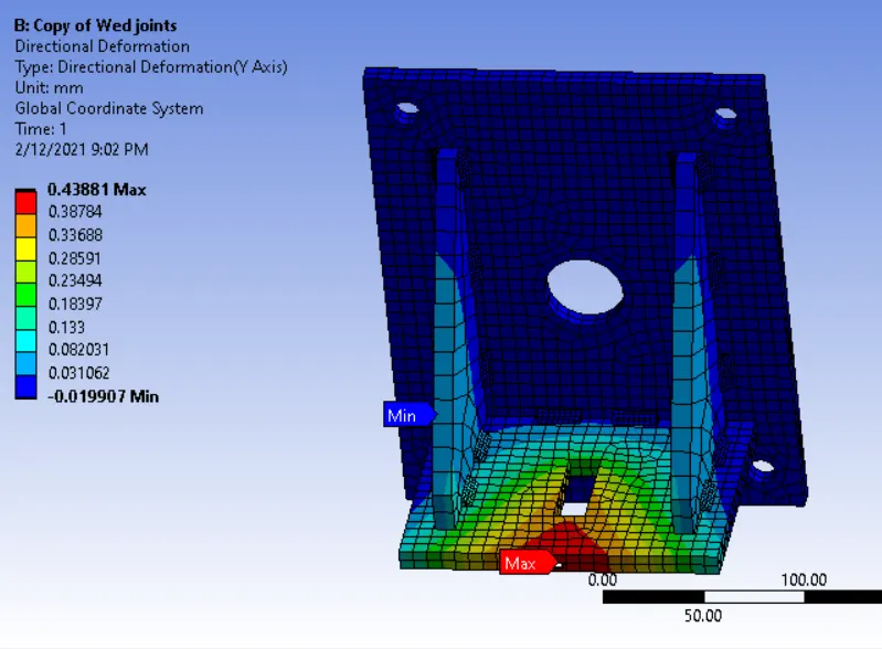
DIRECTIONAL DEFORMATION
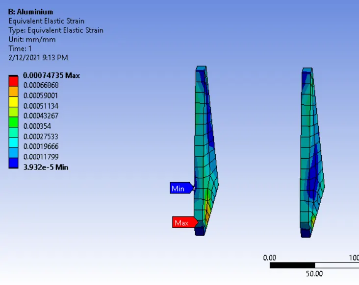
EQUIVALENT ELASTIC STRAIN
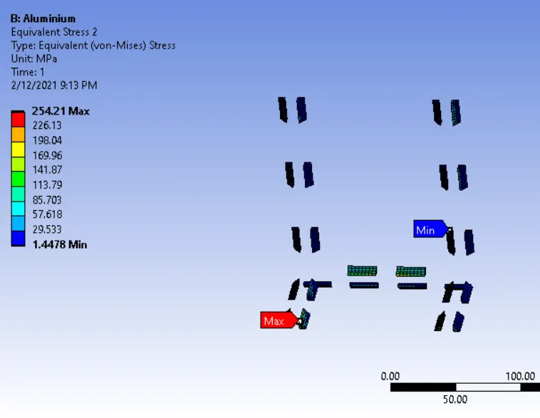
VON MISES STRESS ON WELDS
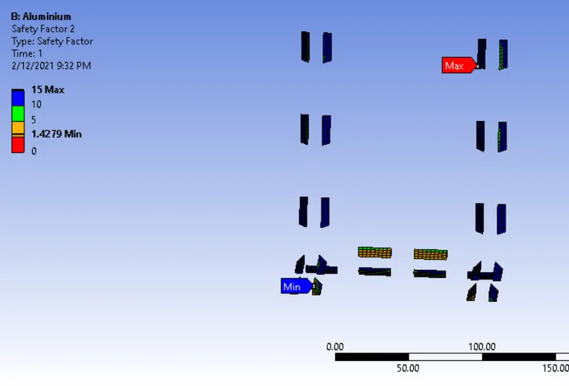
SAFETY FACTOR
Here we can see those having a safety factor of less than 1 would fail but here we have all our weld elements more than 1 hence the design is safe
CASE III: Material used is Bronze
We repeat the same procedures as mentioned for case 1 with different material i.e Bronze as the weld material and Stainless Steel to both plates and Copper to the "Ribs".
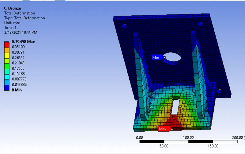
TOTAL DEFORMATION
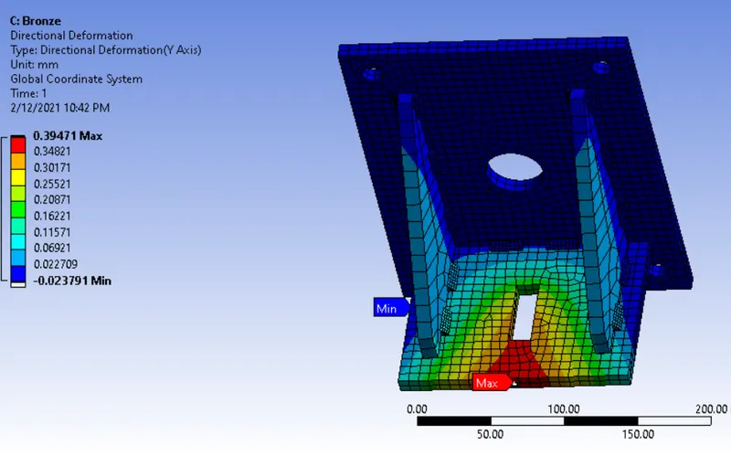
DIRECTIONAL DEFORMATION ON Y-AXIS
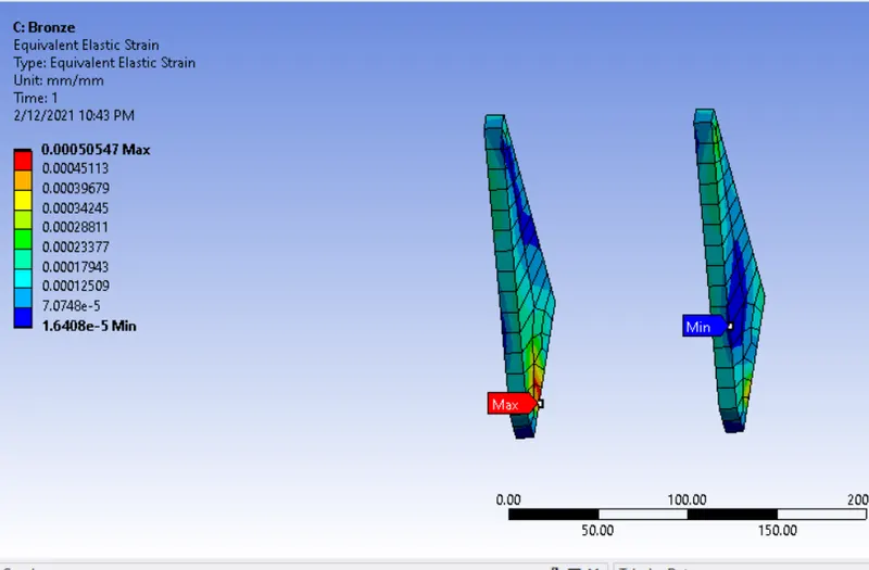
EQUIVALENT ELASTIC STRAIN ON THE RIBS
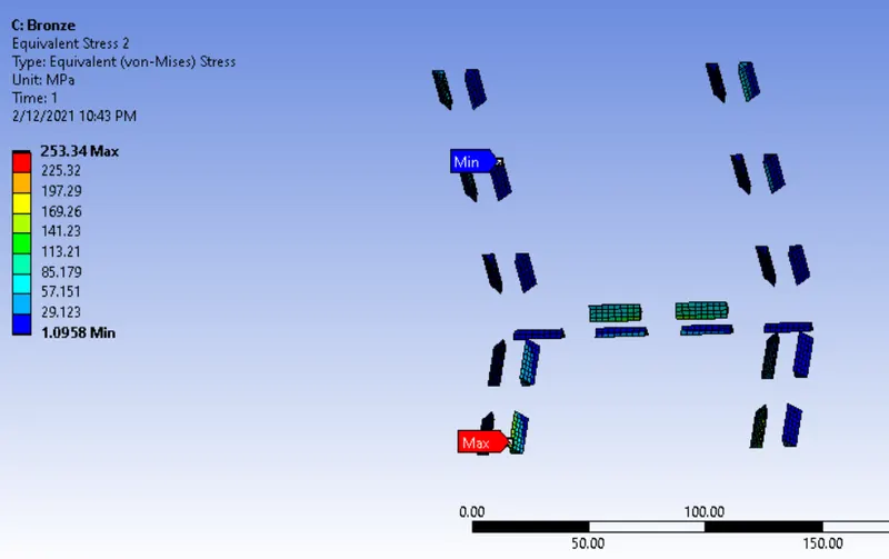
VON MISES STRESS ON THE WELD JOINTS
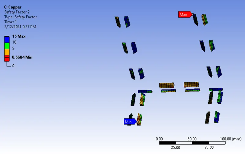
SAFETY FACTOR
Here we can see those having safety factor less than 1 would fail and more than 1 are safe
CONCLUSION:
- The test cases were set up and run successfully
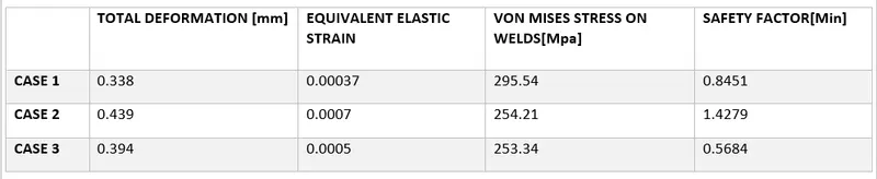
- Considering the above table, the equivalent strain nearly remain the same in all cases with a marginal difference of 0.0001-0.0004
- The deformation is highest in the case of aluminum followed by Structural Steel and Bronze
- The highest stress on weld joint is observed in Structural Steel(Case 1) followed by Aluminium and bronze
- Considering the welds Aluminiu(Case 2) is the most preferred owing to a safety factor of all welds being above 1
Simulation files can be found here