Meshing of car hood
AIM:
Mesh the component given below and assign thickness:
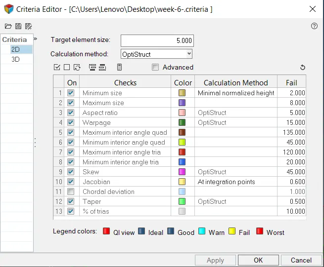
Target Element Length = 5mm
| S.N | Quality Criteria | Value |
| 1 | Aspect Ratio | 5 |
| 2 | Skewness | 45 |
| 3 | Warping | 15 |
| 4 | Taper | 0.5 |
| 5 | Min. Length | 2mm |
| 6 | Max. Length | 8mm |
| 7 | Min angle Quad | 45 |
| 8 | Max angle Quad | 135 |
| 9 | Min angle Tria | 20 |
| 10 | Max angle Tria | 120 |
| 11 | Tria % | 10 |
THEORY:
Computer-aided engineering also known as CAE is the broad usage of computer software to aid in engineering analysis tasks. It includes finite element analysis, computational fluid dynamics, multibody dynamics, durability, and optimization
Meshing is the foundation for all FE based CAE activity. A quality mesh is a prerequisite for reliable CFD and FE analysis projects as is a thorough comprehension of the effects of a mesh on a result. A geometric cleanup helps us to perform meshing efficiently and keep the mesh within the quality criteria
PROCEDURE:
- We import the required model, using the import option and setting up the correct file type
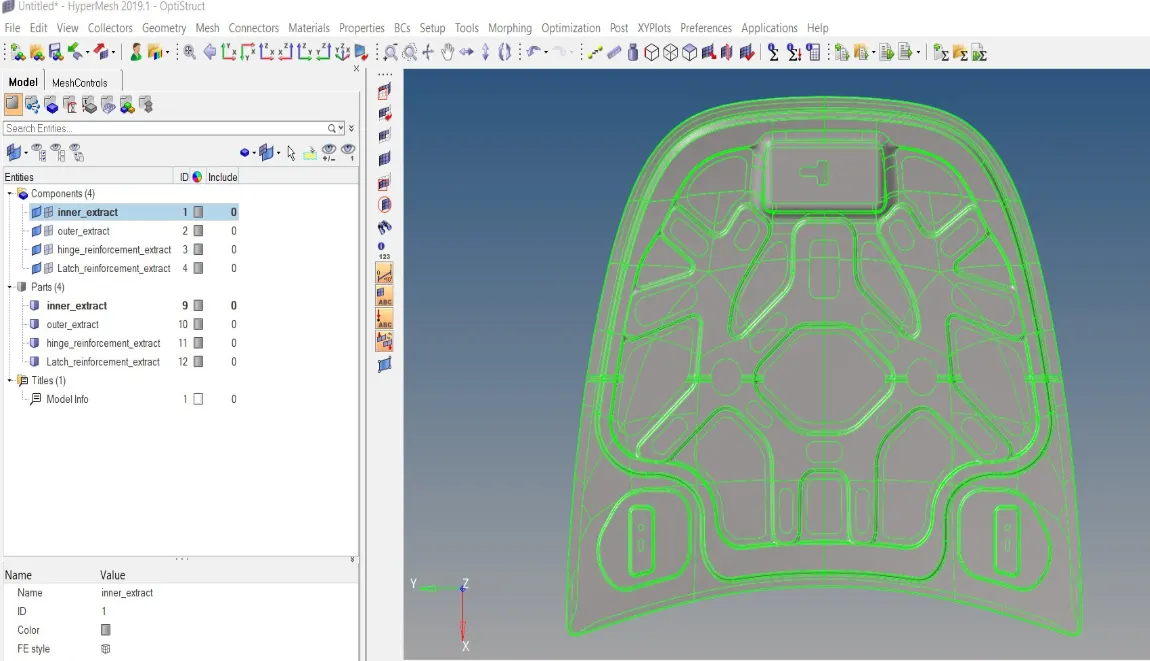
- The imported geometry consists of four components. Here we work on surfaces hence we first delete the solids.
- We do the topology cleanup of each respective component and extract their mid-surfaces using midsurface option in Geometry panel and thereby using auto-midsurface option in mid-surface option

- We work on further cleaning up of the mid-surface component part by part.
- Defeaturing is done to remove the details like surface fillets, edge fillets, pinholes etc to make geometry simpler by using the defeature command
- Now we define material and properties respectively to each mid-surface component
- Next, we set the quality criteria for the mesh to be followed by using the criteria file settings in preference option
- We observe that the outer and inner panels are symmetric components hence we only mesh one half of each component and reflect it to the next half. Also both the hinges are also mirror images of each other hence we mesh one of the hinge and reflect it to the next using reflect option under the tools menu
- Now as we defined the criteria we move forward to mesh with the help of F12 key from our keyboard/ automesh option from our 2d menu is used and set the target element size as 5 and mesh by setting type as mixed to avoid rotating quads and trias to an extent as these distort the mesh flow
- Meshing each component we check the quality of the mesh under quality index option in 2d menu and verify elements abide by the criteria
- Similarly, we mesh all the components and assign the required properties. We have meshed all the components and to view the mesh along with the desired thickness, we change the view to 2d detailed element representation
FINAL MODEL:
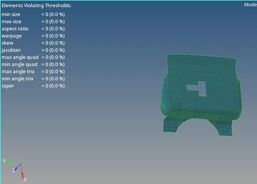
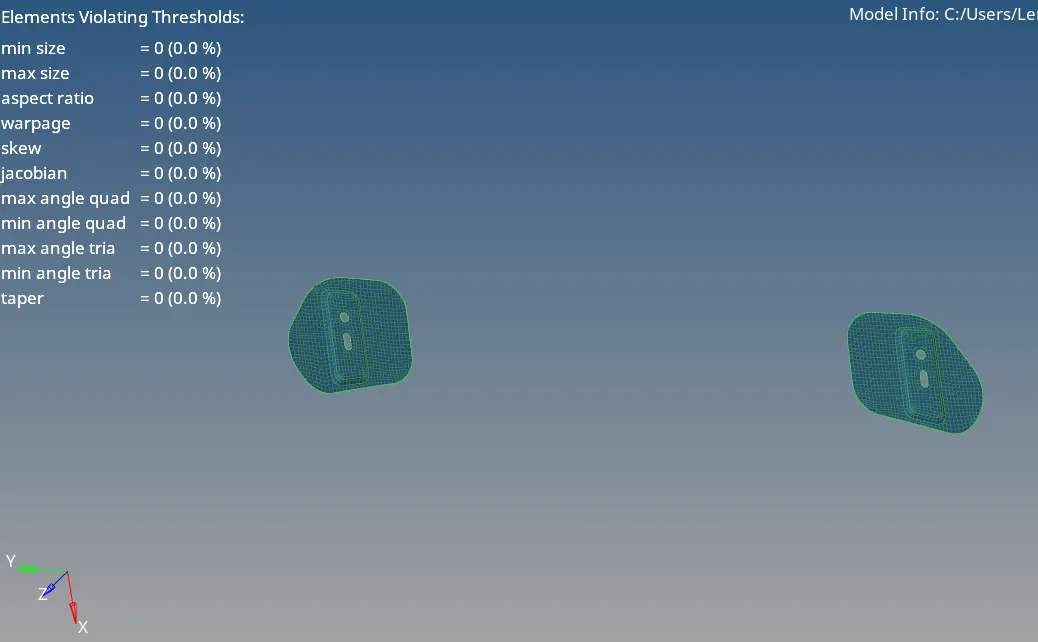
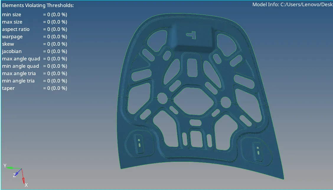
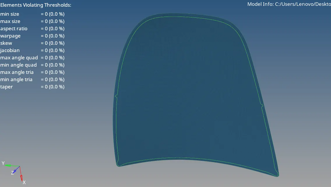
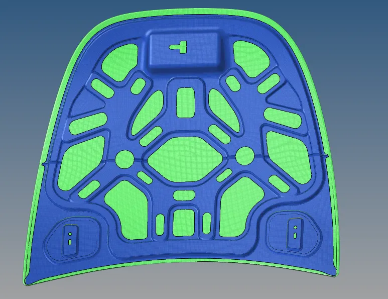
https://drive.google.com/file/d/1OuE7DUm70FTA0Hws-LfW6cWg4CRkr1wp/view?usp=sharing
RESULTS
- The given component is meshed according to the given criteria
- All features were captured properly
LEARNING OUTCOMES:
- Through this challenge, we learn how to mesh components and capture the feature properly
- Keep up with the quality of the elements
- Using the geometry cleanup tools