Connection in a rear door
AIM:
To assign the necessary connections of the rear door model to be simulated for NASTRAN-NVH analysis
PROCEDURE:
Open the file under Nastran input file menu
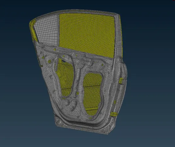
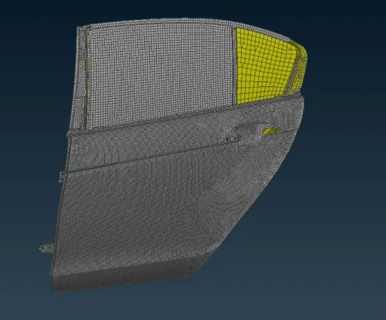
Analyze the model and evaluate the necessary connections to be performed on the model. Also we check for any deformation/cracks using the check manager
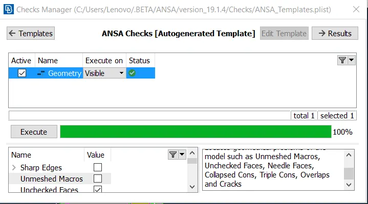
RBE2
In the below hinge model the tops surfaces are connected using cluster rbe2 elements and then the below hinges are connected. The two hinges of the door assembly are connected by hinge pins. For this kind of connection, we must ensure the degree of freedom along Z axis rotational motion is not constrained which makes the doors opening and closing actions. Here connection with the help of two node rbe2.
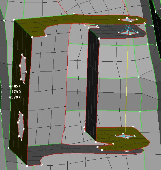
The top parts are connected using rbe2 elements as shown in the figure below. Here this part will be mounted / riveted on the cars body panel. So for NVH analysis, these points are considered as rigid body element(RBE). Here rigid connection is achieved using Many Nodes RBE2 feature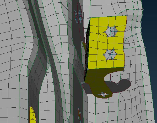
BOLT CONNECTION:
Bolt connection can be achieved by creating a 3D point and realizing it to a bolt connection using the connection manager. Bolts are generally mounted/riveted during door manufacturing along all six degrees of freedom
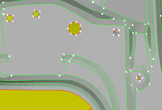
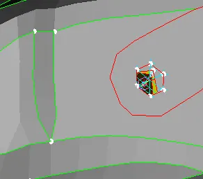
The connection of the door handle is made using Two Node RBE2 and then assigning a mass at the COG using CONMi option in nastaran deck. the mass is entered in terms of tonnes
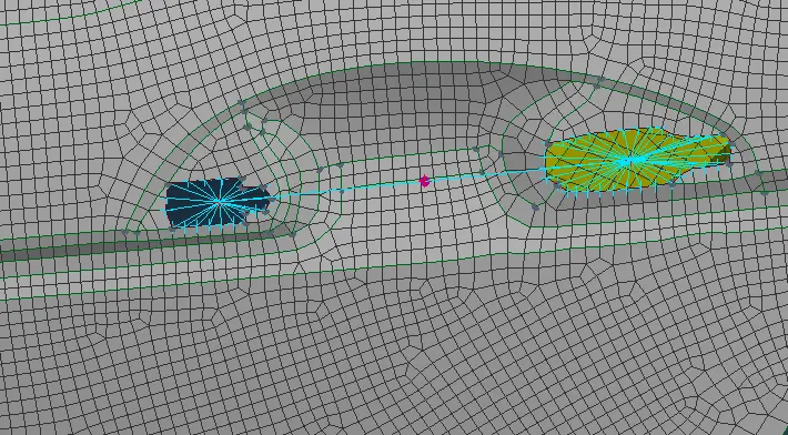
CBUSH Connections:
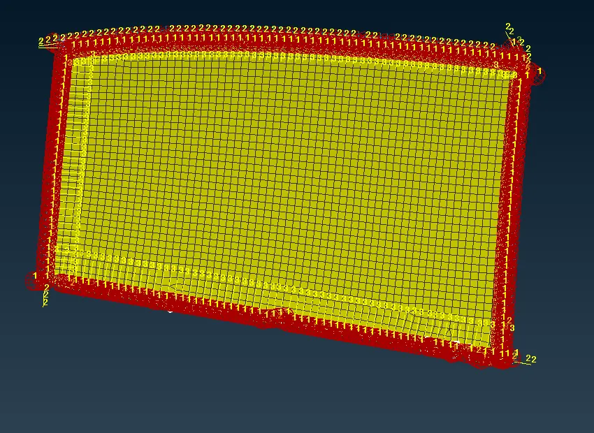
The car window is connected with rbe3-cbush-rbe3 representations to model window the window weather strips. Here the RBE3-CBUSH-RBE3 is used as FE Representation type for these kinds of bush connections.
Y Joint Weld
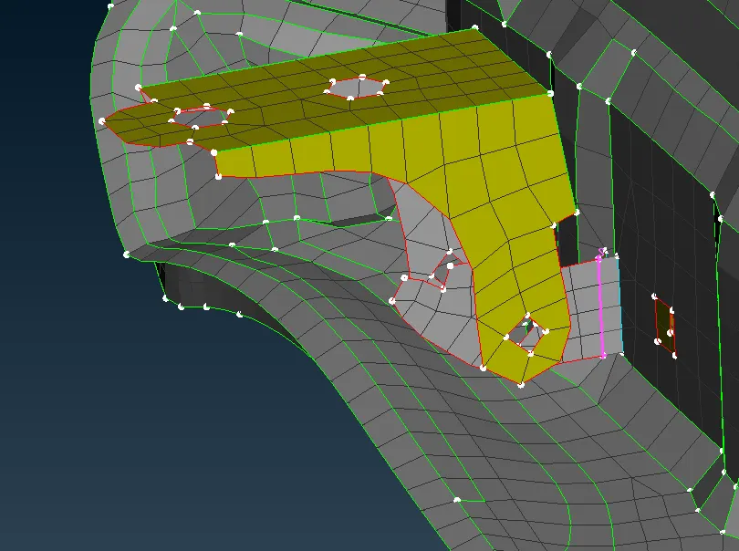
Y-Joint weld connections are used for places where surfaces are perpendicular. This can be achieved by extracting the curve from the FE and later using the connection manager realising it by selecting the two surface to be conected
OVERLAP:
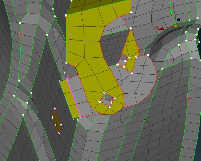
For parallel faces, we use overlap joint weld to connect
SPOTWELD:
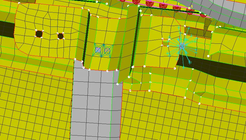
In this rear door assembly brackets with small surface areas are welded together by spot welding. In ANSA 3D points are created then converted to spoteld points and then these points are realised to welds to be applied. For spot welding connection the FE Representation type is set to RBE3-HEXA-RBE3 with RBE Pinflags as 123456 constraining all degrees of freedom
Check if all connections has been applied and realized
RESULTS:
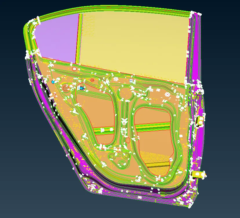
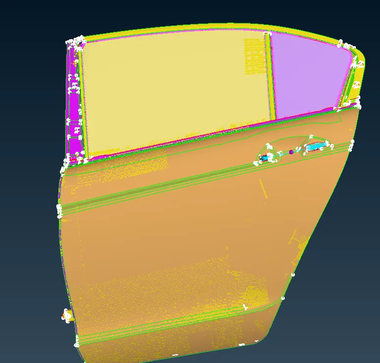
All appropriate connections were made in the FE model of the rear car
LEARNING OUTCOMES:
Learned to assign different connection in a model
Understood the important parameters to consider while assigning connections