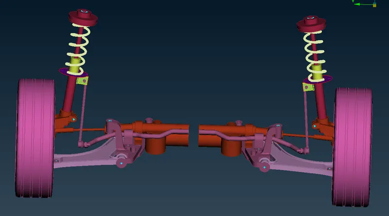
Pre-Processing Of A Rear-Suspension Assembly
AIM:
To mesh the given component according to the below defined quality criteria
INTRODUCTION:
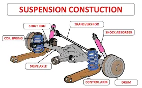
The suspension is the system of tires, tire air, springs, shock absorbers, and linkages that connects a vehicle to its wheels and allows relative motion between the two. Suspension systems must support both road holding/handling and ride quality, which are at odds with each other. The tuning of suspensions involves finding the right compromise. It is important for the suspension to keep the road wheel in contact with the road surface as much as possible, because all the road or ground forces acting on the vehicle do so through the contact patches of the tires. The suspension also protects the vehicle itself and any cargo or luggage from damage and wear. The design of front and rear suspension of a car may be different.
Any four-wheel-drive (4WD/AWD) vehicle needs suspension for both the front wheels and rear wheels, but in two-wheel-drive vehicles, there can be a very different configuration. For fwd cars, rear suspension has few constraints, and a variety of beam axles and independent suspensions are used. For rear-wheel drive cars, rear suspension has many constraints, and the development of the superior, but more expensive independent suspension layout has been difficult. Four-wheel drive often has suspensions that are similar for both the front and rear wheels.
THEORY:
Computer-aided engineering also known as CAE is the broad usage of computer software to aid in engineering analysis tasks. It includes finite element analysis, computational fluid dynamics, multibody dynamics, durability, and optimization
Meshing is the foundation for all FE based CAE activity. A quality mesh is a prerequisite for reliable CFD and FE analysis projects as is a thorough comprehension of the effects of a mesh on a result. A geometric cleanup helps us to perform meshing efficiently and keep the mesh within the quality criteria
We need to take a lot of care for these element qualities as these criteria will make us understand how much the elements are deviated from the ideal element. Since they represent the geometry during a simulation, poor elements will misrepresent the geometry and will lead to inappropriate results.
These are the important quality parameters we should take care
Minimum and Maximum length:
It is the minimum or the maximum length we are maintaining in the mesh generated and should ensure no element goes below or above this criteria
Aspect Ratio:
The aspect ratio is the ratio of Maximum length to the Minimum length.
In simple terms, when you see a quad element one side smaller than the remaining three sides then you will have your element failed for aspect ratio. Being said this,the shape of a perfect quad element has all the sides equal so the ideal value of the Aspect ratio is one.
Due to geometrical constraints not every time, you can achieve a perfect quad and this is exactly why you will be given a tolerance value. This tolerance value depends upon the accuracy required. Having a large aspect ratio will reduce the accuracy of your result.
Skewness:
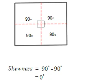
Skewness is the quality of the elements in terms of angles. For a Quad element,
Skewness=90-θ">90−θ90-θ
In case of an ideal quad.
Warpage:
Whenever you have a quad element in two different planes then you will have your element failing for Warpage. Ideally, your element should be in a single plane, when they are in two different planes if you split the quad along the diagonal and measure the angle between the normals it will give your element Warp angle. Warp angle is the angle of plane deviation in your element which is also known as Warpage.
When you have your element failing for warpage then the results of the simulation are going to be inaccurate. Features like fillets are more prone to have a warped element as the geometry itself will be in two different planes. Considering all these geometrical constraints and accuracy we can have a tolerance for this criteria.
Jacobian:
Every element will have its own coordinate system which is known as the Natural Coordinate system. From this coordinate system, it is difficult to derive a direct solution thus these elements' natural system has to be converted to a global system.
So in order to map the elements from their natural system to the global system, these elements have to be in ideal shape.
As we know, not all the time we can have an ideal shaped element in the geometry so tolerance is established. This deviation of the element from the ideal shape is measured through Jacobian. The Ideal value of Jacobian is 1.
Chordal Deviation:
This chordal deviation is the measure of how well the elements captured the curves. When you have a small fillet and if your element size is bigger than the size of the fillet then you can expect this chordal deviation error. You can mesh with a smaller element to capture the fillet or you can increase the tolerance value of chordal deviation considering the accuracy required.
Tet-Collapse
Our main aim while performing 3d tetra meshing is to maintain the tet-collapse which is the distance from the opposite face divided by the area and multiplied by 1.24
TOOLS USED:
Delete: The universal delete function can be used to delete unwanted entities like curves, faces etc
Release: This option helps to release triple cons etc to make it proper
Fill hole: This function fills holes in the faces to fill gaps
Coons-Project: Create curves and project to the surface which is used to patch up the surfaces
Paste: This function is used to paste nodes
Split: This function splits the quadrilateral and triangular shell element into smaller ones
Reconstruct: This tool helps to create a better quality mesh in regions used
Project: This function projects coons or 3d curves onto the faces
Swap: This function helps to swap the shell element to the required destination
Cut: This function helps to cut faces or make splits to bring out uniform mesh in the model
Extend: This tool helps to join required faces to another face
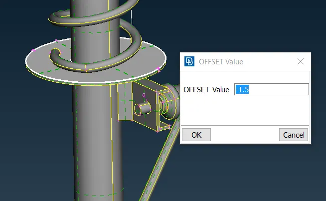
Offset: This function helps to take mid-surface of the components
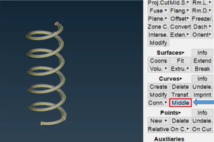
Middle: This tool helps to take mid surface in between of two components
Fix Quality: This is used to clear the tet-collapse automatically
PROCEDURE:
Import the given model onto ANSA
- Geometric cleanup
First of all we have to perform Topo on the given model to stitch the surfaces together using the Faces->Topo option

MODELLING OF THE SHELL MESH COMPONENTS:
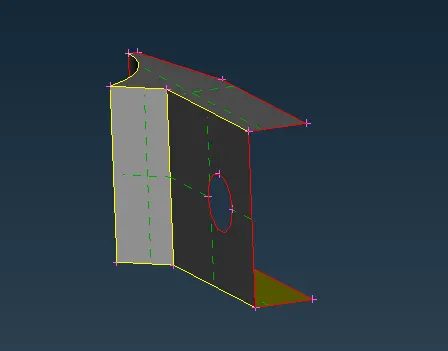
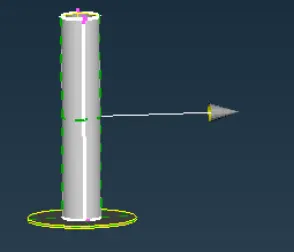
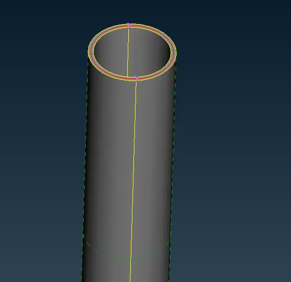
The below-shown parts midsurfaces can be extracted using the Faces->skin option
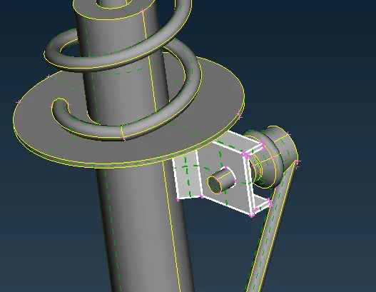

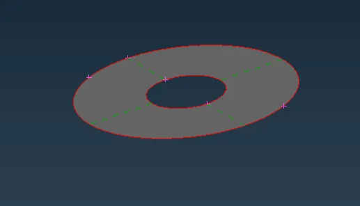
The following circular disc mid surface can be extracted using the Faces->offset command
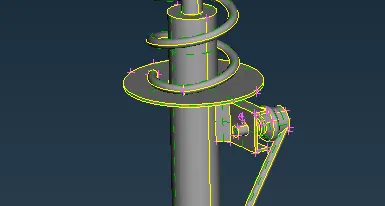
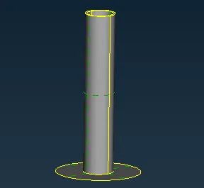
The cylinder attched to the circular dics too can be shell meshed. Hence we first extract the mid surface
MESHING:
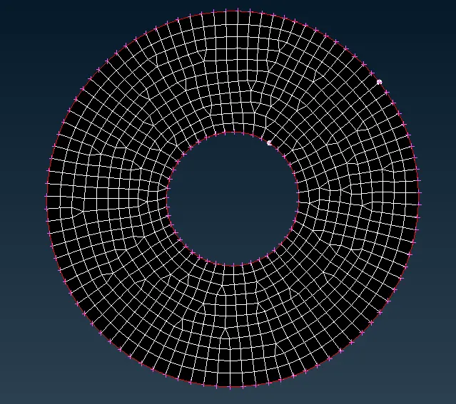
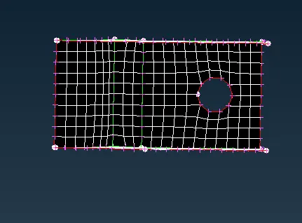
The above models can be meshed using the Mesh->Mesh Generation->Spot Mesh option. Then we use the reconstruct option there to get a good mesh flow
MODELLING OF A SPRING
The spring here can be modeled as a 1D element. For this, we generate a middle curve using the middle option
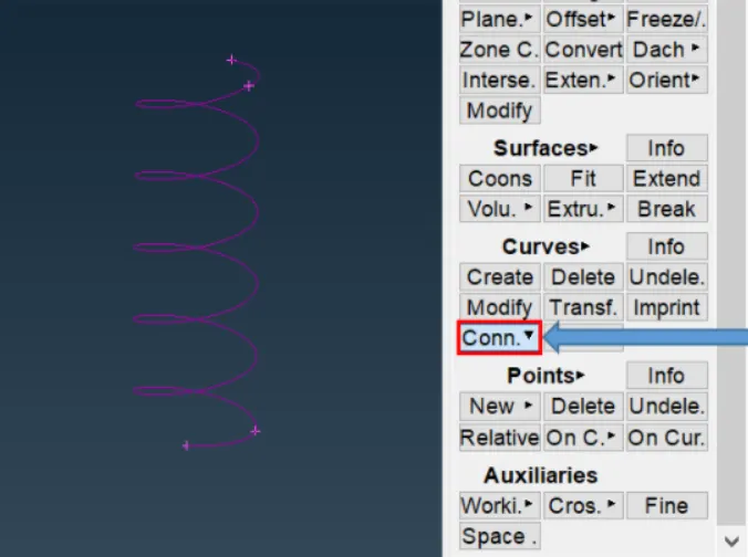
Then connect the respective obtained curve into a single curve using the Curves->Connect->Multi option
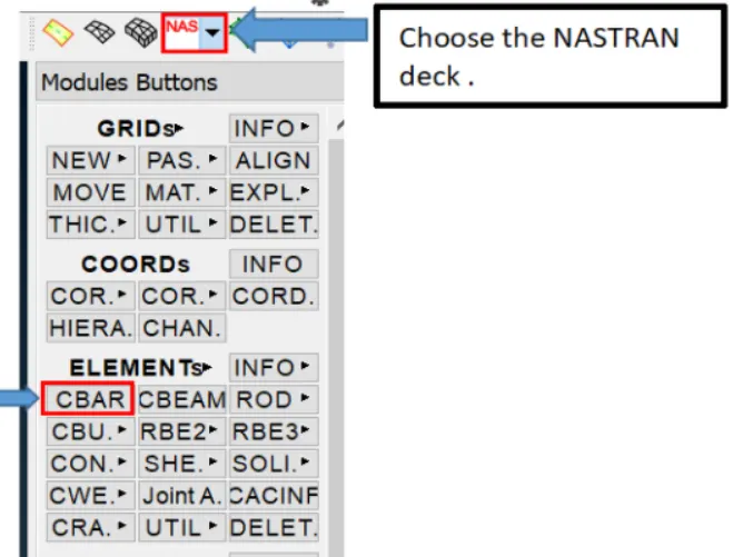
We then create a COG point for the spring to define orientation. Next we select the CBAR option in the Nastran deck
We set the selection type to curve box and select the made curve and select the orientation node and thereafter we have to specify the length
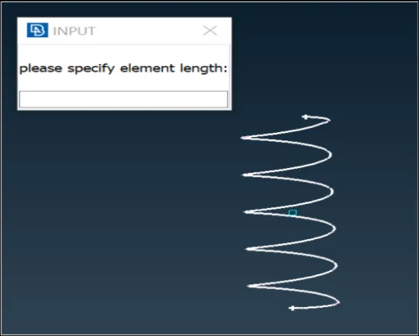
After setting the length as 3mm we then create a new PID for this component. We enter the radius of the component and respective all other properties are derived by ANSA itself
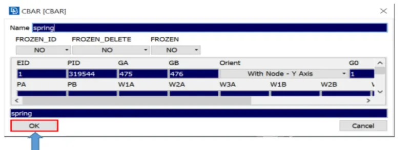
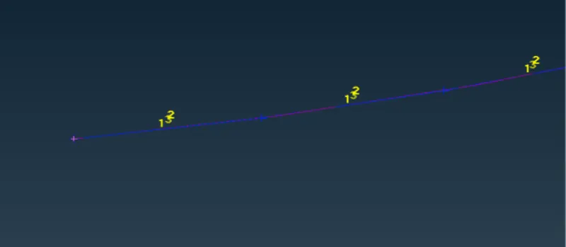
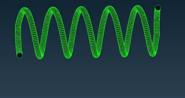
CBAR elements are created. We then turn on draw line elements cross-section->as solid on and a detailed view of same is obtained
MODELLING OF THE 3D MESH COMPONENTS
The remaining parts here are to be tetra meshed as they have a thickness above 5mm
Firstly we mesh the components using tria and ortho trias elements respectively with a target of 4 mm. Ortho Trias are generally used on features such as fillets, chamfers etc for better mesh capturing
Then a volume is defined for each component using Vol Mesh->Define option and then the property is defined using Vol Mesh-> List and then using the remesh option using the Terta rapid/Tetra FEM algorithm we can convert the tria mesh to tetra mesh
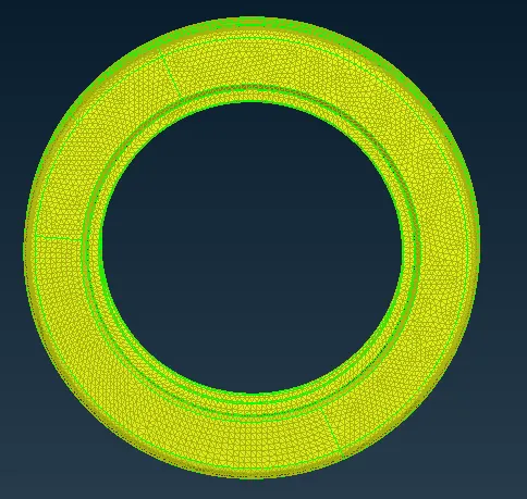
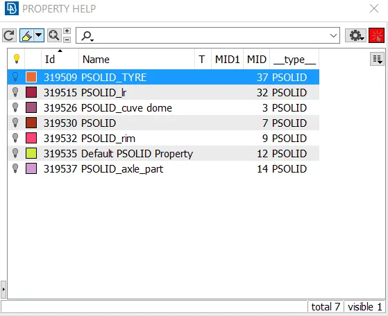
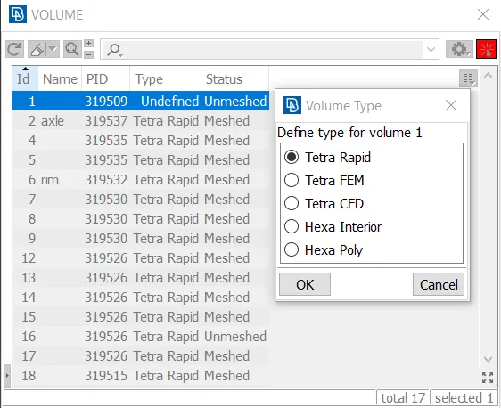
The tetra meshed can be viewed by masking some part of any respective components
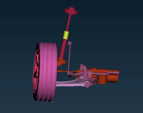
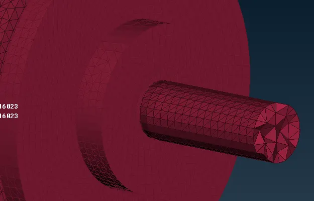
Tetra Meshed Assembly Masking of elements to view tetra elements
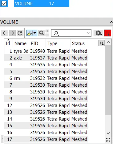
We can see all our volume meshed components in the Database tab
CONNECTIONS:
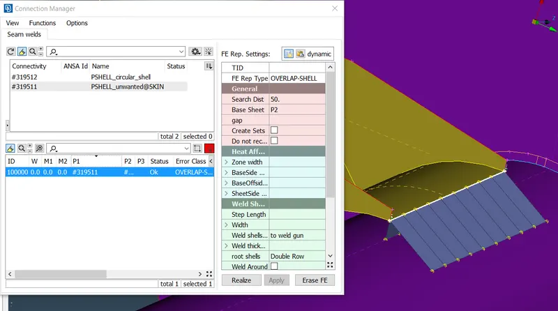
Here we can deploy a seam weld. This can be achieved by creating a curve and then defining the curve as a seam line. Then via the connection manager selecting P1 and P we can get it realized
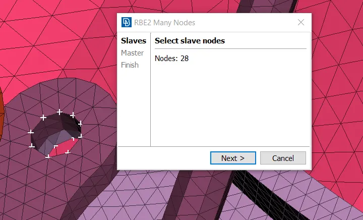
For bolt connection we first connect the elements using NASTRAN->RBE2-> Many Nodes and the stem representation can be achieved using two-node rbe2
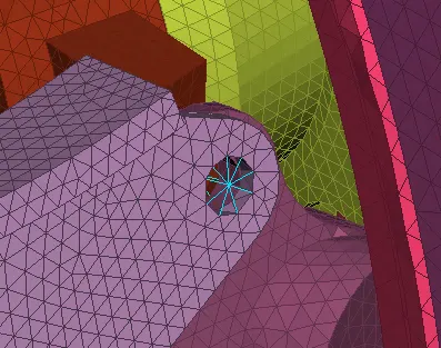
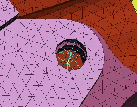
Similarly, all other connections are deployed using RBE2 option
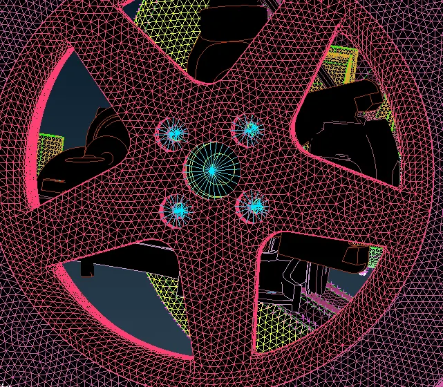
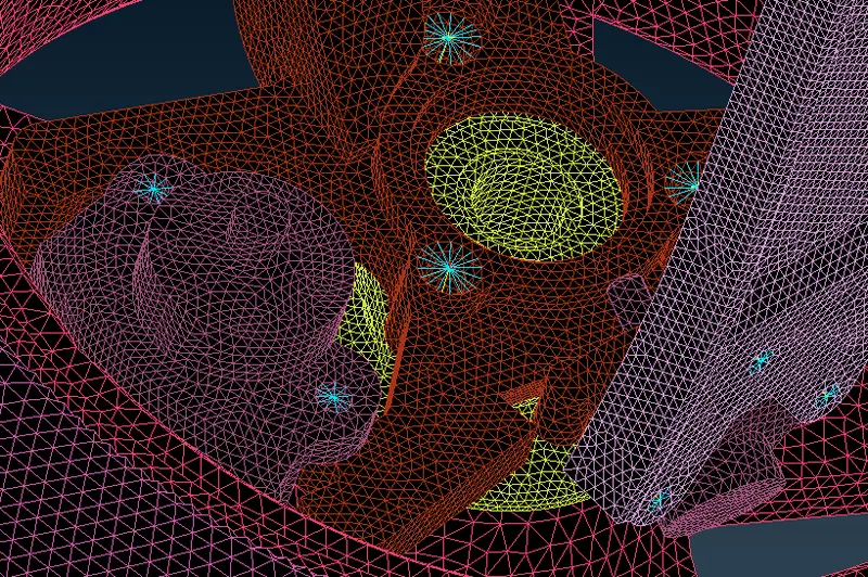
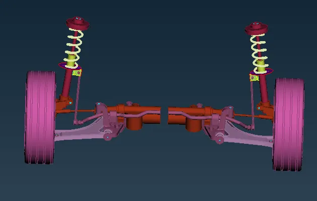
Finally the component can be mirrored to obtain the full suspension assembly using the Transform->Copy->Symmetry
RESULTS:
The rear suspension assembly was meshed and required connections were deployed