Rolling operation
AIM:
To perform a copper rolling sheet simulation using Ansys workbench
THEORY:
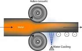
In metalworking, rolling is a metal forming process in which metal stock is passed through one or more pairs of rolls to reduce the thickness, to make the thickness uniform, and/or to impart a desired mechanical property. The concept is similar to the rolling of dough.
For copper cold rolling and foil rolling, several types of mill are selected according to the rolling process, thickness and materials to be produced. Our typical mill type is the UCM-Mill, which is suitable for rolling to thin gauge. The alternative X-Mill technology is another of our typical mill type for thin copper and copper alloy foil rolling. 4Hi, 6Hi, 12Hi CR mill and 20Hi ZR cluster mill are also applied by us for cold rolling of copper and copper alloys.
PROCEDURE :
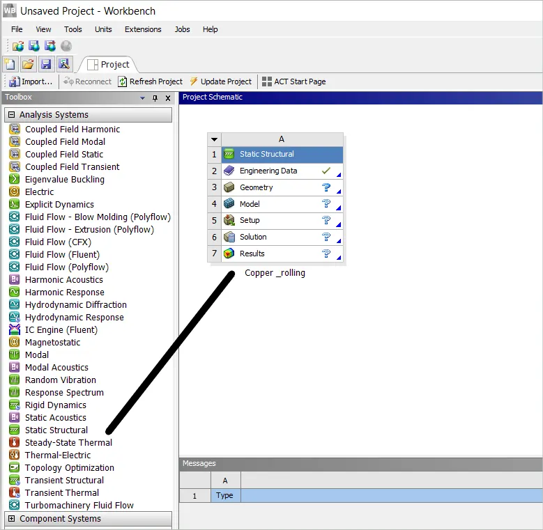
We import the static structural module by draging it into the ansys workspace and rename it as copper_rolling
• In engineering data select the specified materials. In this case. Copper Alloy NL from general Non-linear Materials. Both rollers are defined with structural steel as the material and workpiece is deined with COPPER NL
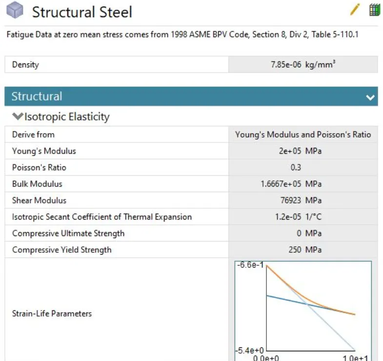
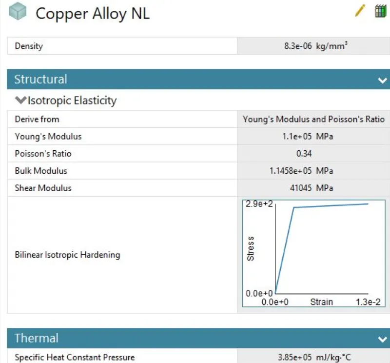
MATERIALS USED FOR THE ANALYSIS
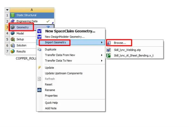
• Open the Design modeler or spacelaim and import the geometry to check for any deformations or errors. It can be done using Geometry-->Import Geometry-->Browse and the geometry gets imported then its opened in Spaceclaim
• Increase the length of the workpiece by 60 mm and decrease the breadth by 8 mm on both sides. Then Close the design modeler. We increse the size of the workpiece by Edit-->Pull option
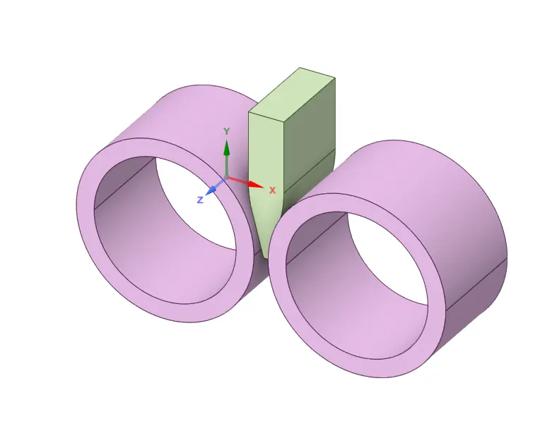
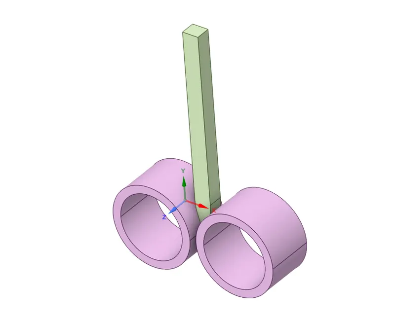
INITIAL GEOMETRY FINAL GEOMETRY AFTER THE MODIFICATION
• Open Mechanical Solver and specify Copper material to the Workpiece. All the parts here are named randomly hence we use F2 key and rename the components
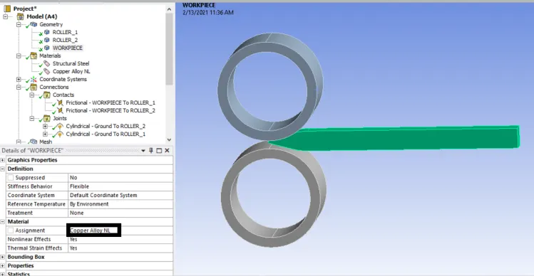
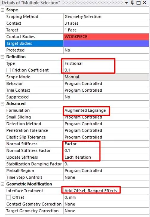
• Apply contacts and joints for the model appropriately. The contacts are frictional with a 0.2 frictional coefficient and joints are cylindrical body-grounded joints.
• Mesh the model appropriately. Apply sizing option for the Workpiece of 4 mm to apply sizing we goto mesh-->insert-->sizing
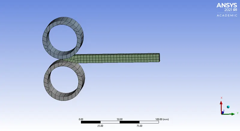
MESHED MODEL
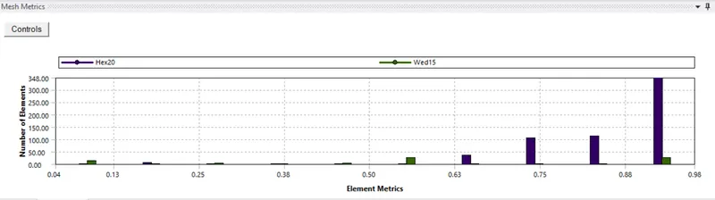
MESH METRICS
• In analysis settings apply displacement to the workpiece in the negative Y direction in which workpiece progresses during the simulation. Also apply joint rotations to the wheels. It is also ensured that both rollers rotate in the opposite direction
Roller -1
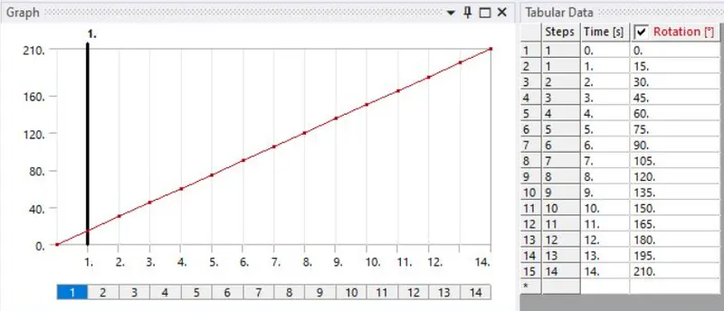
Roller-2
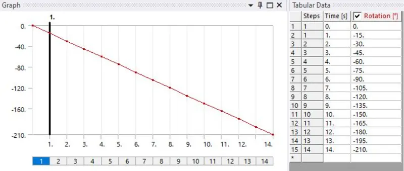
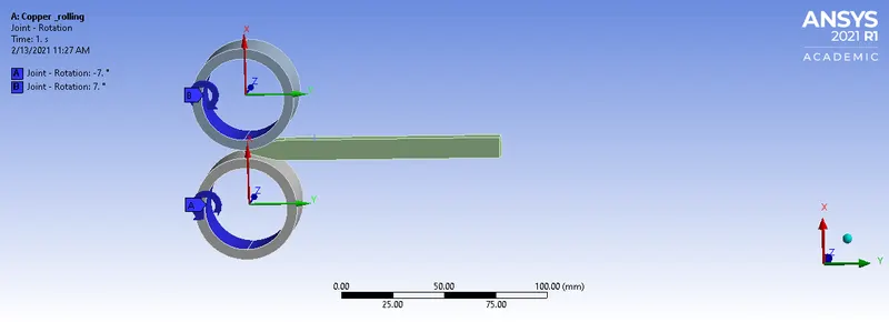
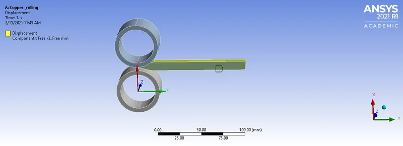
DISPLACEMENT APPLIED TO THE WORKPIECE IN -Y DIRECTION
• Now for results. apply equivalent stress, equivalent plastic strain for Workpiece, directional deformation in Z direction, and directional deformation of the tip of Workpiece.
• After applying Click on Solve to find the simulation results.
RESULTS:
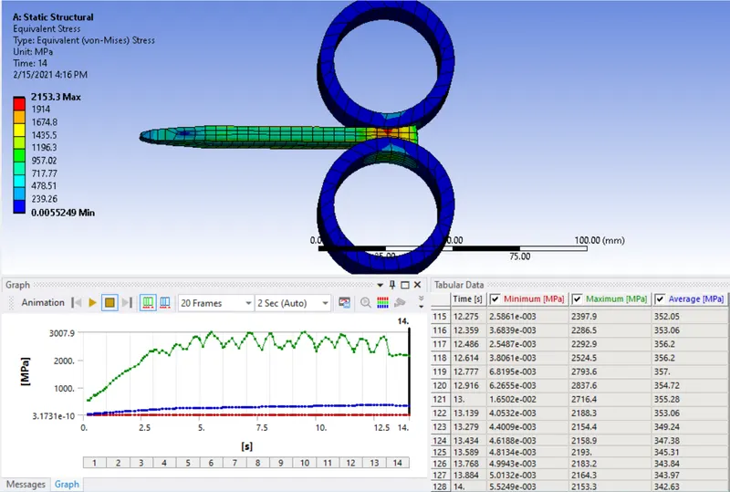
VON-MISES STRESS
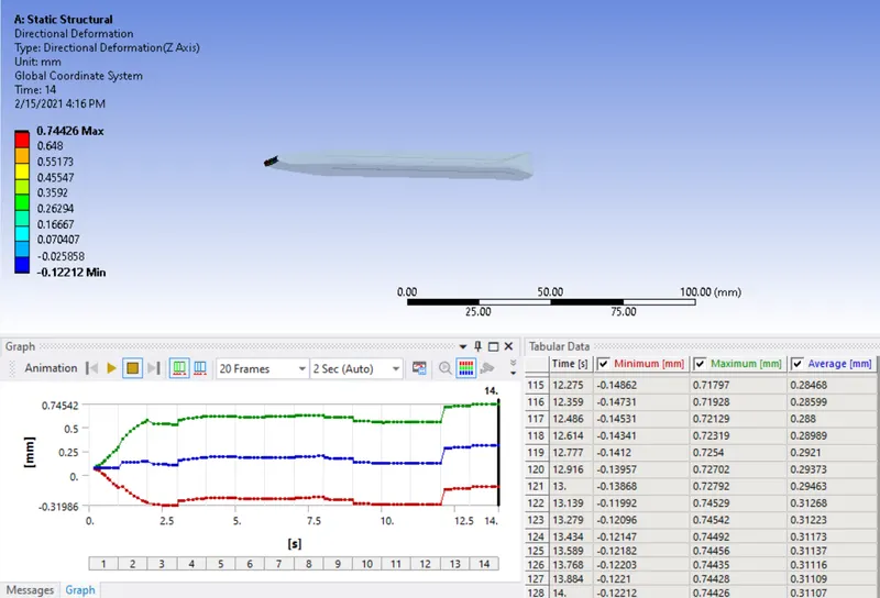
Directional Deformation in Z-axis
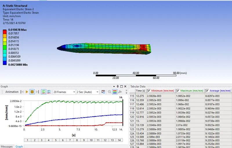
EQUIVALENT ELASTIC STRAIN
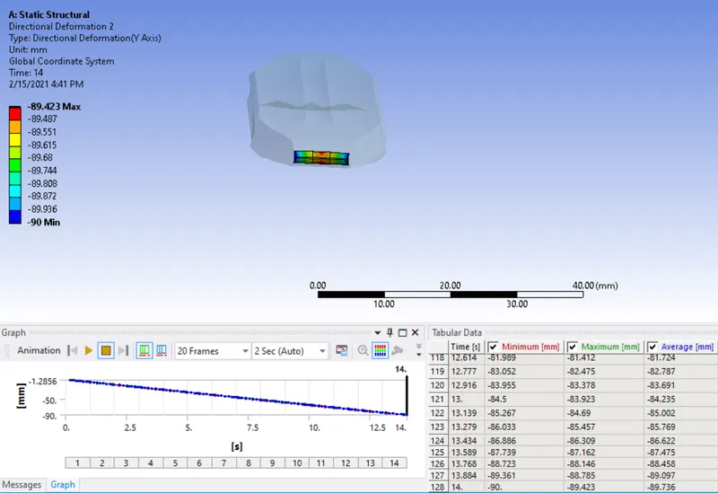
Directional Deformation in Y-axis
CONCLUSION:
The test case was setup and run successfully
Equivalent plastic strain and equivalent stress has been found out
A maximum of 0.74mm directional deformation was observed in the Z axis for the workpiece
The workpiece has been displaced nearly by 90mm during the simulation