Week 2 - Flow over a Cylinder.
AIM:
Simulate the flow over a cylinder and explain the phenomenon of Karman vortex street.
INTRODUCTION
Vortex Shedding: Vortex shedding is an oscillating flow that takes place when a fluid flows past a blunt body at certain velocity. In this flow the boundary layer separated from the surface forms a shear layer which roll into vortex and detach from the surface whereas in Von Karman Vortex Street shedding occurs from both the sides of the body which interact with each other. They shed alternatively from the cylinder and generates a regular vortex pattern called Karman Vortex Street.
Strauhal Number: Strauhal number is the non dimensional number describing the oscillating flow mechanism.
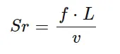
where Sr is Strauhal Number
f - frequency of oscillation in Hz L - characteristic length in m. In this case L = D, where D is the diameter of the cylinder in m. v - velocity in m/s Large Strauhal number indicates that the viscosity dominates the flow whereas lower Strauhal number indicates high speed fluid. Drag Coefficient. Drag Coefficient is a dimensionless quantity that is used to quantify the resistance of an object. It is used in the drag equation which lower drag coefficient indicates less aerodynamic or hydrodynamic drag.
Drag Coefficient
Drag Coefficient is a dimensionless quantity that is used to quantify the resistance of an object. It is used in the drag equation which lower drag coefficient indicates less aerodynamic or hydrodynamic drag. 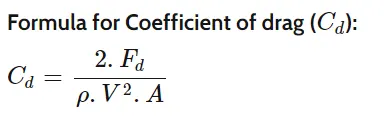
where Fd is drag force in N. p- density of the material in Kg/m3 V - velocity of the inlet flow in m/s A - area of the object in m2, here A is area of cylinder with diameter 2m.
Lift Coefficient.
The lift coefficient is a non-dimensionaless quantity that relates to the lifting force to the density of the fluid and velocity of the fluid and associated area of the object. The formula for Coefficient of lift(C/)
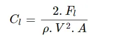
Where Fi is the lift force in N. p - density of the material in Kg/m3 V - velocity of the inlet flow in m/s A - area of the object in m2, here A is area of cylinder with diameter 2m.
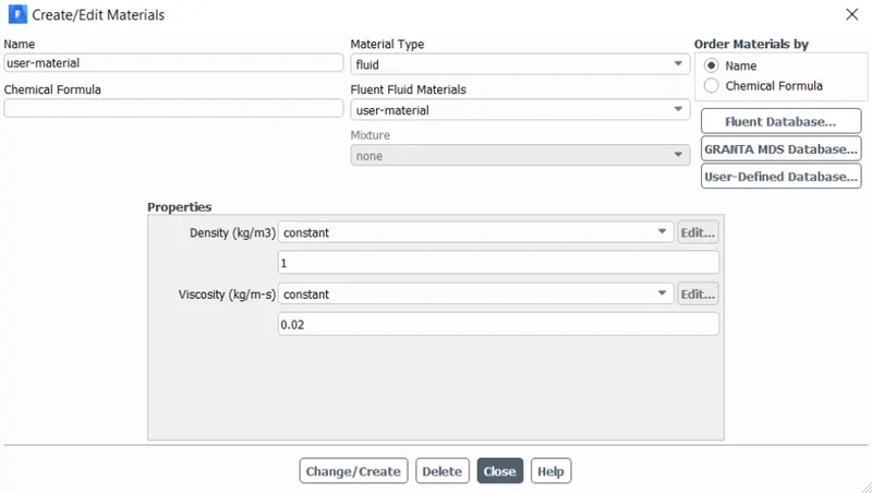
MATERIAL USED
BOUNDARY CONDITIONS
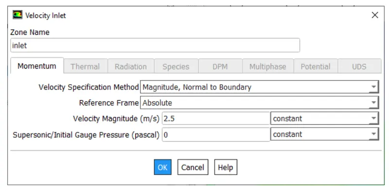
INLET BOUNDARY FLOW CONDITION
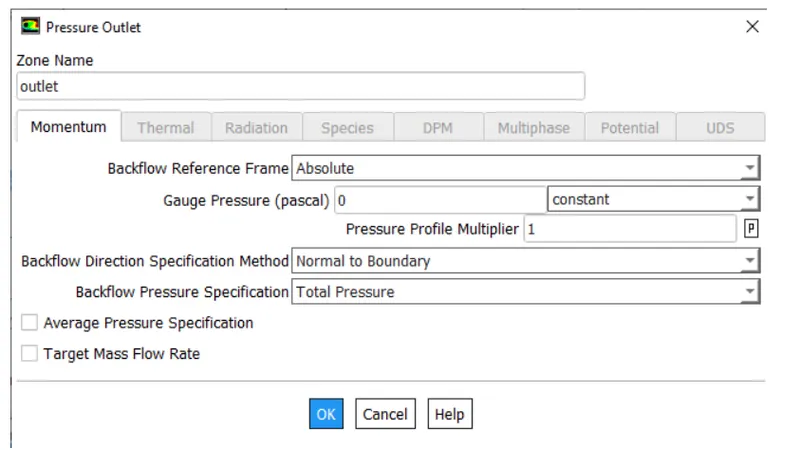
OUTLET BOUNDARY CONDITION
PROCEDURE:
We open Ansys workbench fluent module
Then we create a cylinder in ansys spaceclaim.Below is the figure of the model we would be using
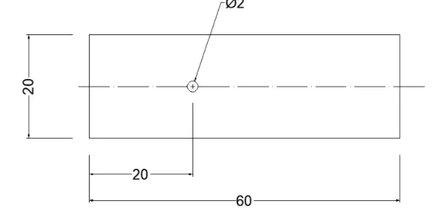
We then open the meshing module and mesh this with a refined mesh. Here we set a traingular mesh as it is generally preferred for CFD meshing
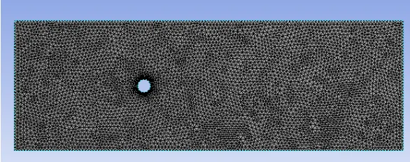
Since the flow around the cylinder is more important so inflation layers are also included. This helps in creating body titted mesh as it completely fits the mesh where the first layer thickness is 0.005m with growth rate of 20%.
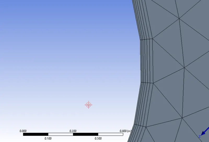
Now we close the meshing module and move on to setup. Here we set the required solver and boundary conditions and move forward to solve the solution
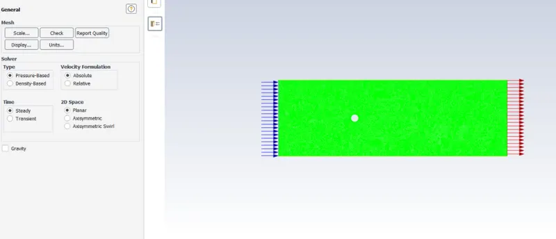
STEADY SIMULATION SELECTION
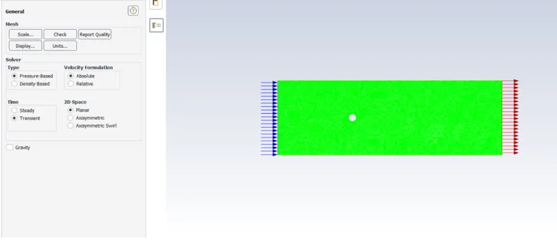
TRANSIENT SIMULATION SELECTION
We set the solution scheme to simple and the required reference values for the simulation.For 2D simulation deph is always 1
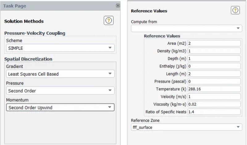
Now after initializing the solution we can move on to solve our solution
RESULTS
CASE I: STEADY STATE
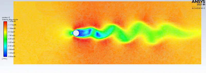
VELOCITY CONTOUR
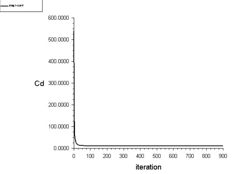
Coefficient of drag
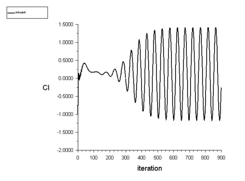
Lift coefficient
For the steady case St cannot be found out as in steady-state the flow does not vary with time it cannot be found out
CASE II:
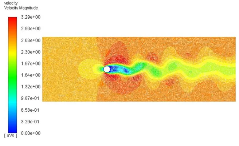
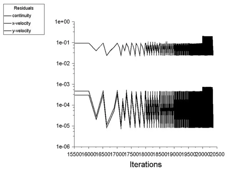
RESIDUAL PLOTS
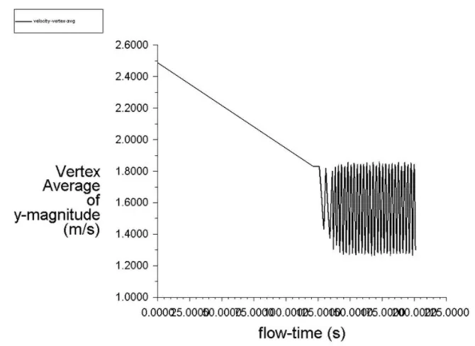
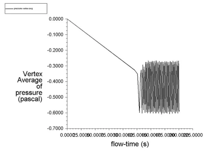
VERTEX AVERAGE OF VELOCITY AND PRESSURE
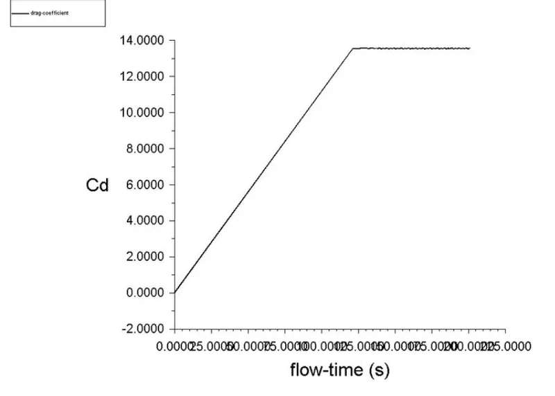
COEFFICINET OF DRAG
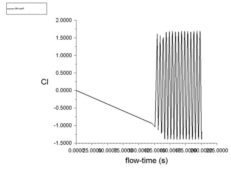
COEFFICIENT OF LIFT
The Strouhal Number calculated is
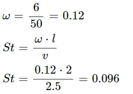
Hence its 0.096 for a velocity of 2.5 m/s
PART II
CASE I: Re 10
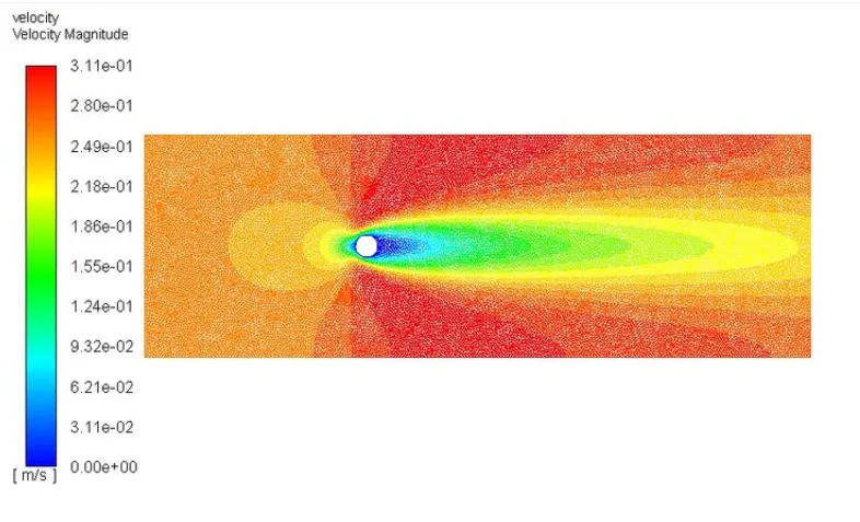
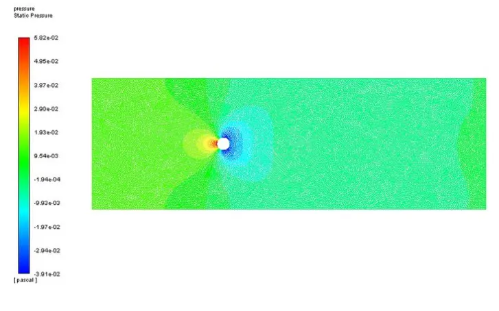
VELOCITY CONTOUR PRESSURE CONTOUR
CASE II:Re=100
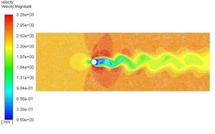
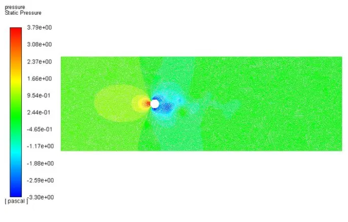
CASE II:Re=1000
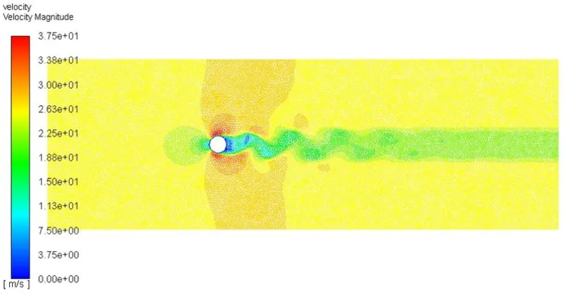
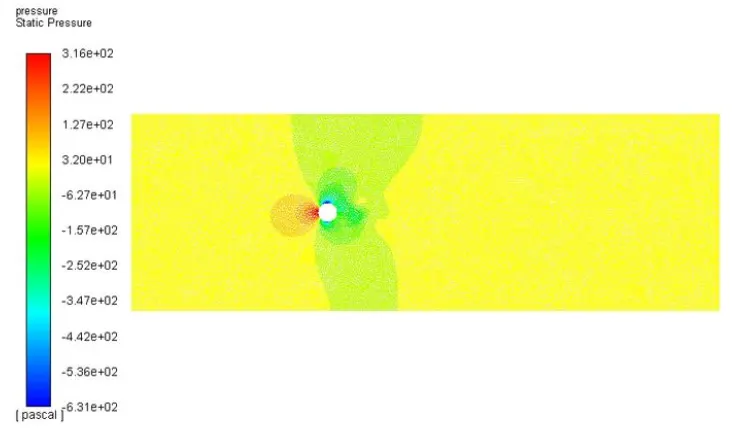
CASE II:Re=10000
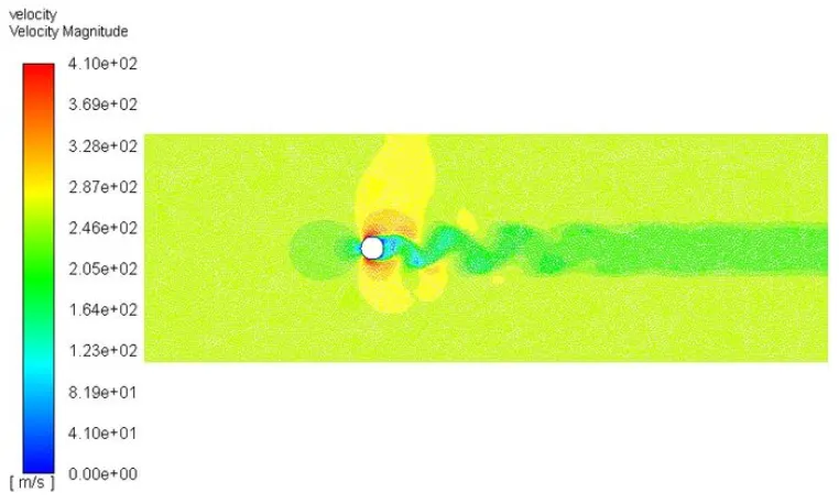
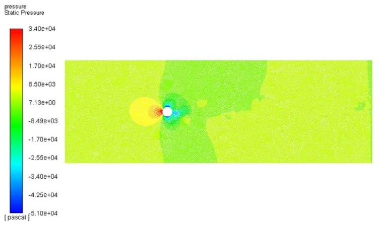
CASEII:Re=100000
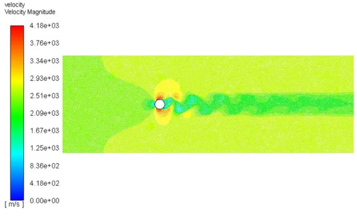
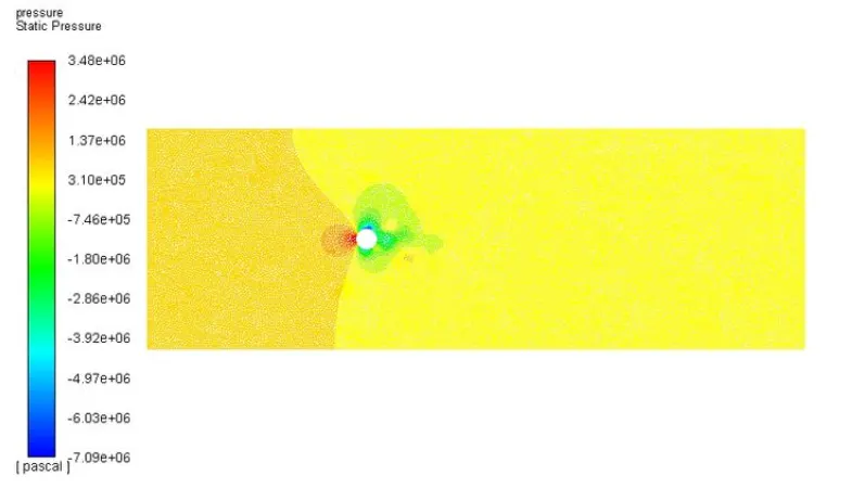
At RE no.=10 no vortices can be seen, only boundary layer separation can be seen which is indicated by deep blue colour. As the RE no. increases the boundary layers separation decreases which indicate that there will be less recirculation of flow at the wake region behind the cylinder thereby decreasing the drag. For this simulation all the parameters are kept constant except for the velocity, so increasing the velocity will increase the RE no. This high-velocity flow carries away the vortex street and decays after some distance.

CONCLUSION:
1. The convergence of the flow solution not only depends upon residual plot but majorly on the steadiness of the lift graph. The convergence and stability observed in lift graph purely symbolizes the onvergence in solution.
2. The negative lift coefficient indicated downward application of force. Or acting in opposite manner in which direction vector.
3. Coefficient of drag decreases as the Reynolds number increases.
4. The CL variation/oscillation increases with an increase in Re
Referred Research Paper:- https://www.sciencedirect.com/science/article/pii/S0307904X08000243