Spur Gear Challenge
OBJECTIVE:
To perform various analyses on spur gear and conclude a better material based on our analysis. Casewise analysis is to be performed in which we are given 3 material which has to be assigned and studied.
THEORY
Spur gears or straight-cut gears are the simplest type of gear. They consist of a cylinder or disk with teeth projecting radially. Though the teeth are not straight-sided (but usually of special form to achieve a constant drive ratio, mainly involute but less commonly cycloidal), the edge of each tooth is straight and aligned parallel to the axis of rotation. These gears mesh together correctly only if fitted to parallel shafts. No axial thrust is created by the tooth loads. Spur gears are excellent at moderate speeds but tend to be noisy at high speeds
MATERIALS USED
CAST IRON
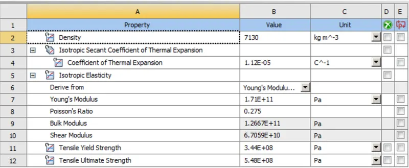
CAST IRON MATERIAL CARD
BRONZE
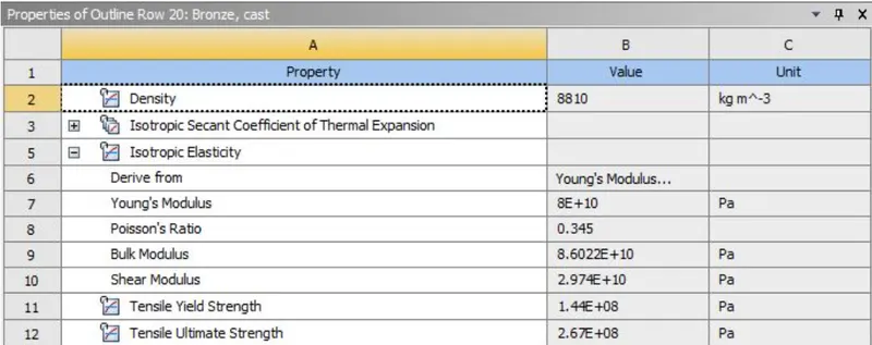
BRONZE MATERIAL CARD DEFINITION
CAST STEEL
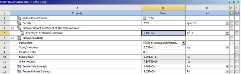
CAST STEEL MATERIAL CARD DEFINITION
PROCEDURE
Import the STP file and assign engineering data to it. We have 3 cases according to which the materials has to be assigned.
Case 1— Assign material Cast iron and calculate the equivalent stress, Total deformation & stress intensity.
Case 2- Assign material cast bronze and calculate the equivalent stress, Total deformation and stress intensity
Case 3- Assign material Carbon steel and calculate for equivalent stress, stress intensity and total deformation.
For each and every case we have to solve individually and capture data. We first open the workbench. Then drag and drop static structural module
Starting with Gray cast iron. Gray cast iron material can be found in General material section of engineering data.
After material selection edit the model in Mechanical workbench. Initially rename the gear according to their side, like right for right-hand side gear and left for left-hand side gear.
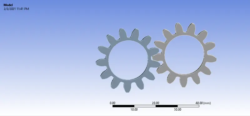
Gears opened in mechanical module
After renaming Contacts and joints has to be assigned. We assign a frictional contact here selecting all tooth faces of respective gears which will come in contact
• For defining contacts between two gears, select faces of left gear as "Contact" and faces of right gear as "Target" for connection.
• There are 26 faces of each gear, must be selected.
• Select Contact type = Frictional. Because due to friction, there will be movement between gears.
• Select Behavior = Symmetric
• Select Formulation = Augmented Lagrange. As soon as teeth come in contact, it will tend to move from its position. So, Augmented Lagrange formulation reduces vibration and penetration and increases stiffness of gears.
• Select Interface Treatment = Adjust to Touch. Because if there is a gap between them or initial penetration, than this setting will help to adjust it and any error can be avoided.
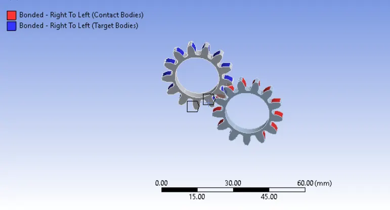
Now we have to request the needed solution outputs. We goto Solution-->Total Deformation/Von mises stress/Equivalent Strain
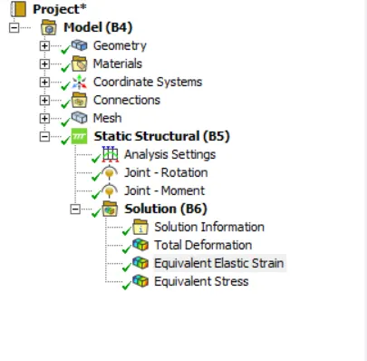
We then hit the solve button and set the number of cores to 4[according to the computer capacity]
CASE I:
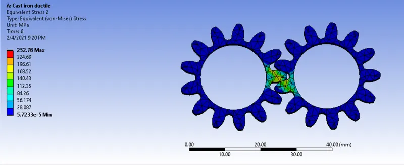
EQUIVALENT STRESS
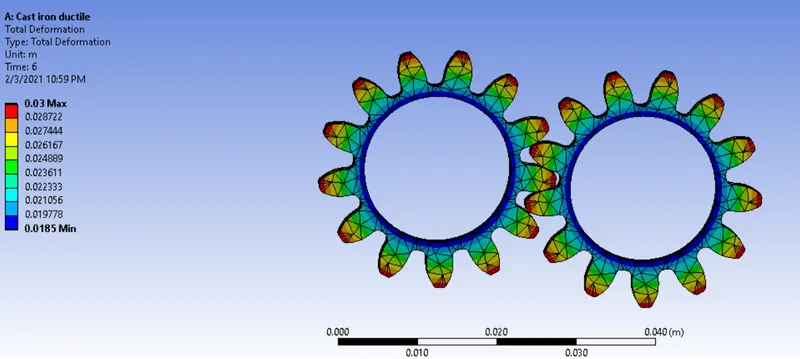
TOTAL DEFORMATION
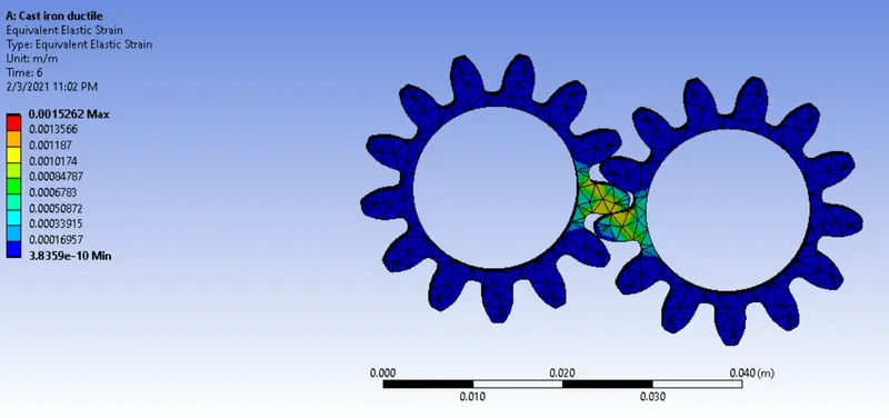
EQUIVALENT STARIN
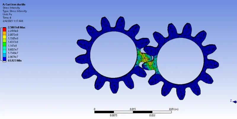
STRESS INTENSITY
CASE III:
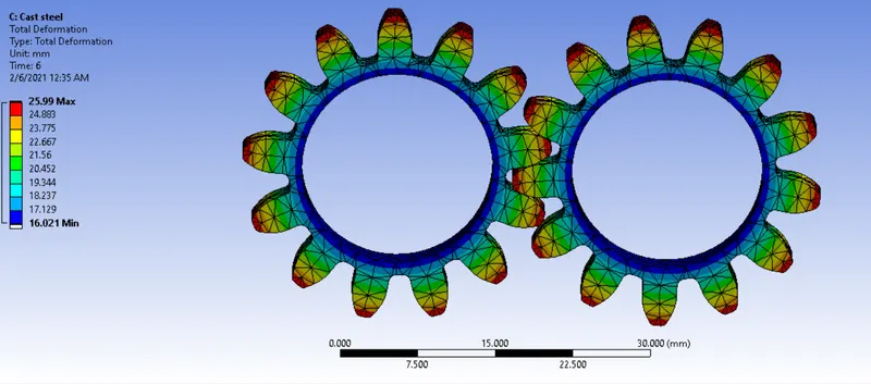
TOTAL DEFORMATION
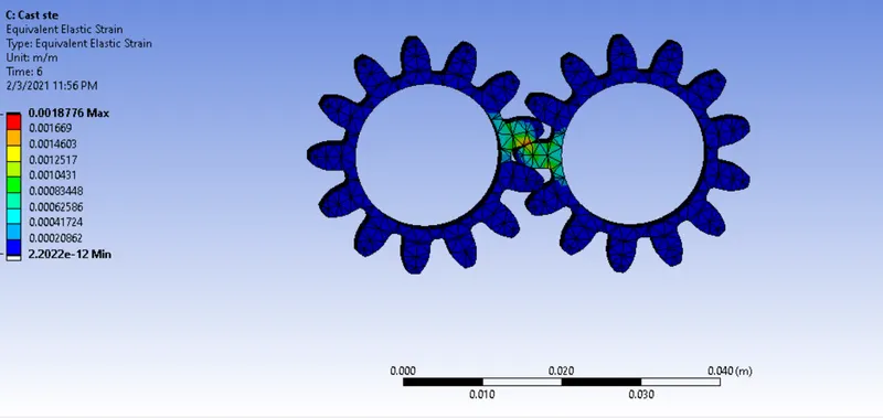
EQUIVALENT STRAIN
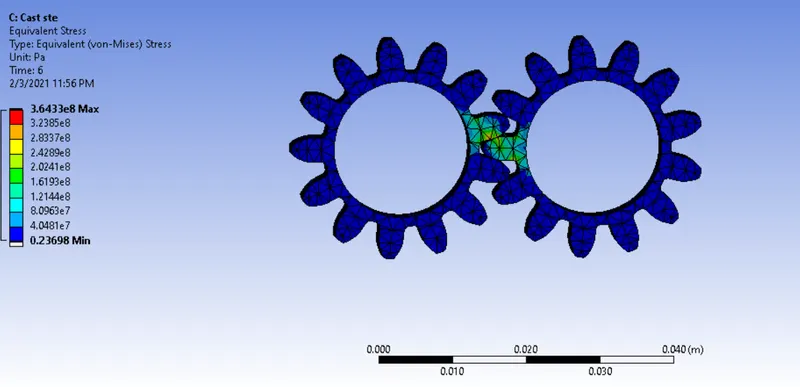
VON-MISES STRESS
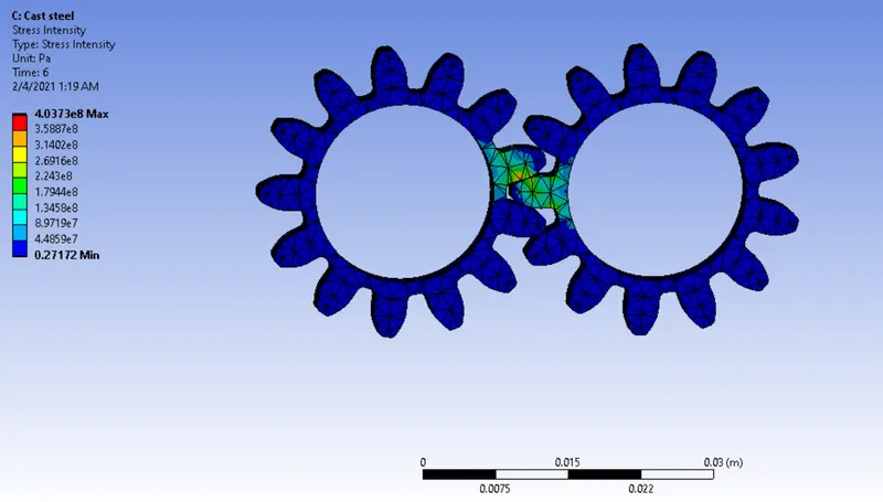
STRESS INTENSITY
CASE III:
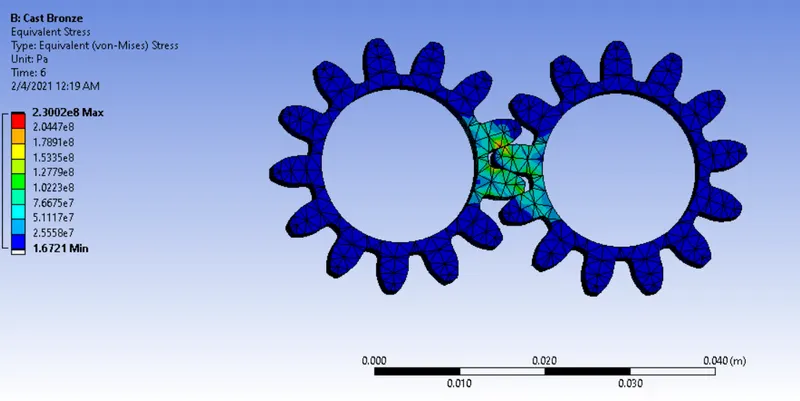
VON-MISES STRESS
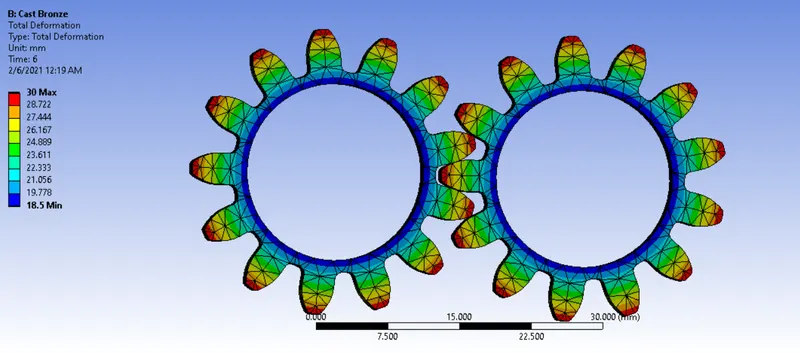
TOTAL DEFORMATION
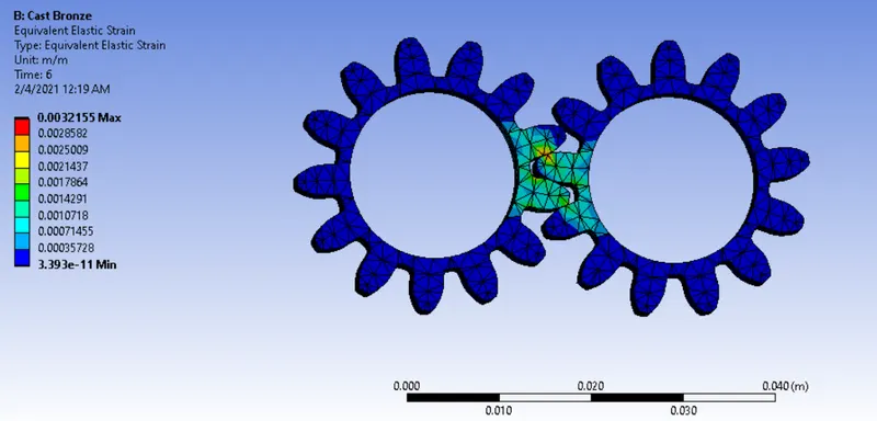
EQUIVALENT STRAIN
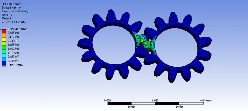
STRESS INTENSITY
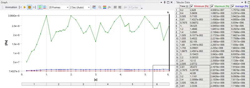
CAST IRON
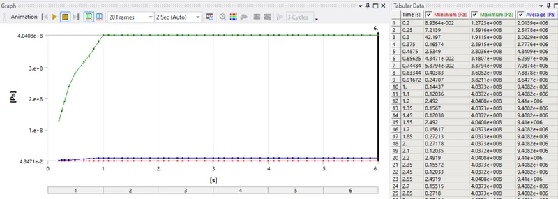
CAST BRONZE
CAST STEEL
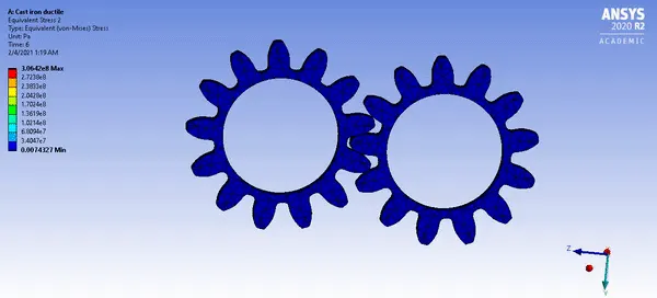
CAST IRON VON MISES STRESS CONTOUR
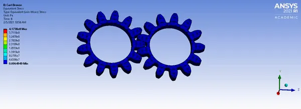
CAST BRONZE VON MISES STRESS CONTOUR
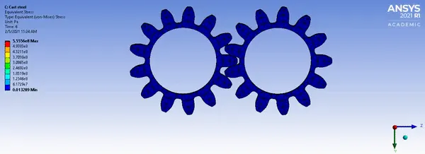
CAST STEEL VON MISES STRESS CONTOUR
| MATERIAL | TOTAL DEFORMATION(mm) | EQUIVALENT STRESS(Pa) | STRESS INTENSITY(Pa) |
| CAST IRON | 30 | 2.52E+08 | 2.58E+08 |
| BRONZE | 30 | 2.3E+08 | 3.35E+08 |
| CAST STEEL | 25.99 | 3.6E+08 | 4.03E+08 |
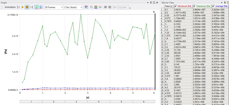
The maximum equivalent stress is higher for cast steel which is 360 MPa followed by grey cast iron and cast steel with values 252 MPa and 230 MPa respectively. The stress intensity is highest for cast steel with a value of 403.02 MPa followed by cast bronze and gray cast iron with values 335 MPa and 258 MPa respectively. We can observe the same deformation in Iron and bronze and a slightly less value for steel
The stress intensity factor in fracture mechanics is used to predict the stress state near the tip of a crack or notch caused by a remote load or residual stress. Essentially it gives the stress variation in cracks or notch or tip of the material. There is a considerable difference between the screenshot values and gif values. This is because of dynamic values obtained during the gif values. For convenience, the screenshot values are taken for comparison.
As we can see here gears have a number of notches or fillets in their profile for load transmission stress intensity is a vital factor in the design of gears
CONCLUSION:
From the above results, it can be seen that cast steel fails more quickly than other materials since it has more stress intensity and also has higher equivalent stress. The crack formation or failure for the same number of cycles is quicker in the case of cast bronze since it has higher stress intensity values compared to iron. So, it is the least preferred material Between gray cast iron and bronze, the equivalent stress is higher for gray cast iron but the value of stress intensity is less. Also, as discussed above the crack formation or failure for the same number of cycles is quicked for cast steel when compared to gray cast iron since the value of stress intensity is higher for cast steel.
Also as discussed above grey cast iron has the lowest stress intensity too. Therefore, going by the above trade-off grey cast iron is the most preferred material
The simulation files can be found here