Structural Meshing of the Car Spare Wheel Holder using Hypermesh
AIM:
To mesh the given component according to the below quality criteria
Target Element Length = 5mm
| S.N | Quality Criteria | Value |
| 1 | Aspect Ratio | 5 |
| 2 | Skewness | 45 |
| 3 | Warping | 15 |
| 4 | Taper | 0.5 |
| 5 | Min. Length | 2mm |
| 6 | Max. Length | 8mm |
| 7 | Min angle Quad | 45 |
| 8 | Max angle Quad | 135 |
| 9 | Min angle Tria | 20 |
| 10 | Max angle Tria | 120 |
| 10 | Tria % | 10 |
THEORY:
A spare tire (or stepney) is an additional tire (or tyre - see spelling differences) carried in a motor vehicle as a replacement for one that goes flat, has a blowout, or has another emergency. Here we are going to mesh a spare wheel holder
PROCEDURE:
Import the CAD model into hypermesh
We import the required CAD model to hypermesh with RADIOSS as user profile using the import geometry in meu bar
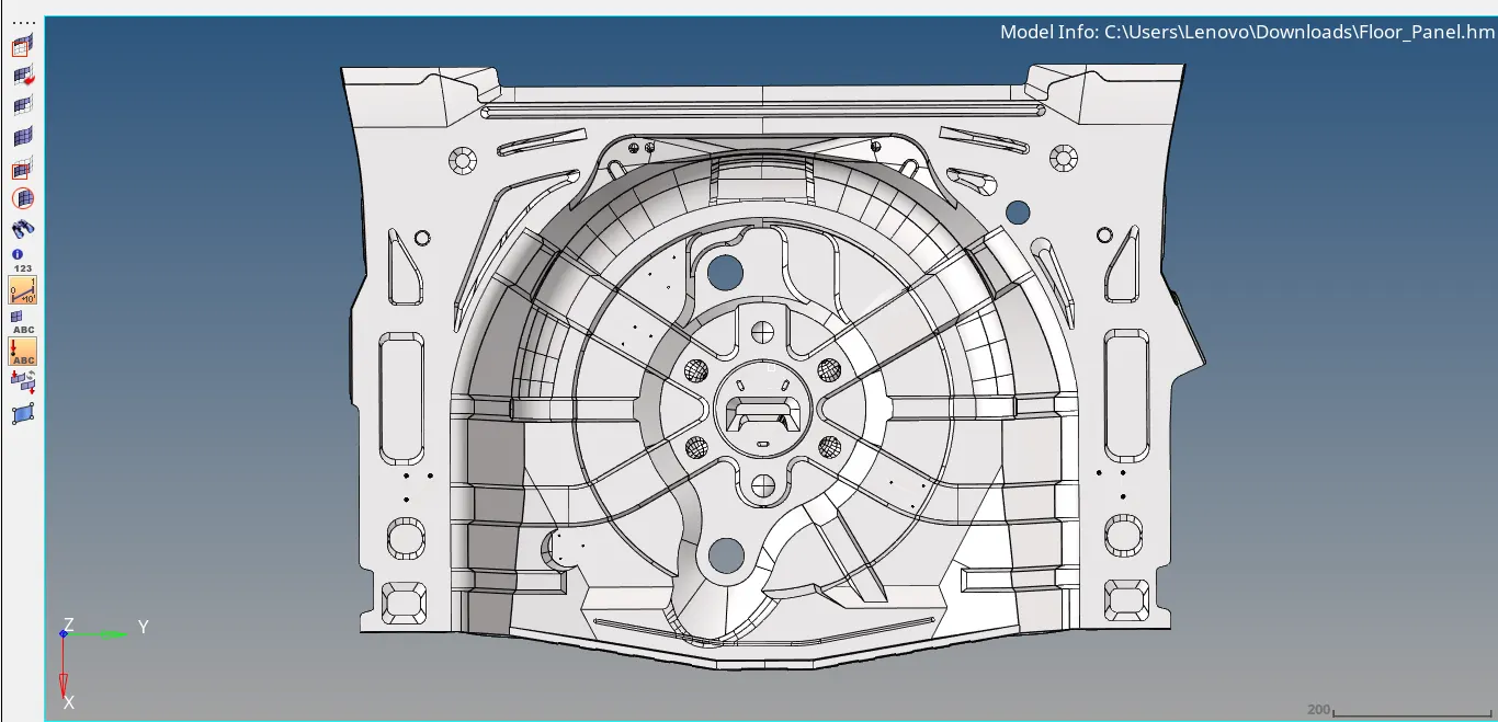
Geometry clean up of the model
To get a proper mid surface we clean up the model and fix all deformations and other such issues such as fixing gaps between surfaces. Here in this model, we can see some free edges and t-connections which should be corrected using the toggle command in the quick edit panel.
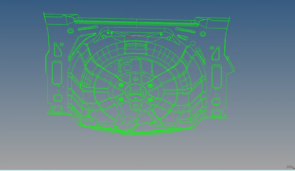
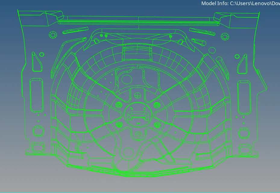
Mid-surface extraction of the component
Extraction of mid-surface using various techniques. Here as different parts are of different thickness and not uniform manual mid surface extraction is an ideal way for extracting the mid surface
Meshing if the mid surface
Here we perform 2d mesh on the mid-surface. In order to perform 2d mesh we go to 2d panel and select the auto-midsurface option with a target element length of 5 and the mesh type as mixed
Eliminate the elemental failures as per the quality criteria
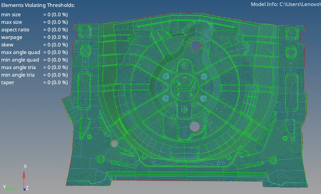
After meshing we ensure the mesh generated is followed within the quality criteria. We can check this using the quality index option in the 2D panel. Here in this mesh we avoid rotating quads in mesh and also tries near fillets and free edges
Apply the required thickness and convert the shell elements into solid elements
Here we individually apply thickness to each every part corresponding to their parent component. The thickness we assign for component can be done in the properties panel by setting the required thickness and assigning to the component. Here the thickness is 0.75
MODEL:
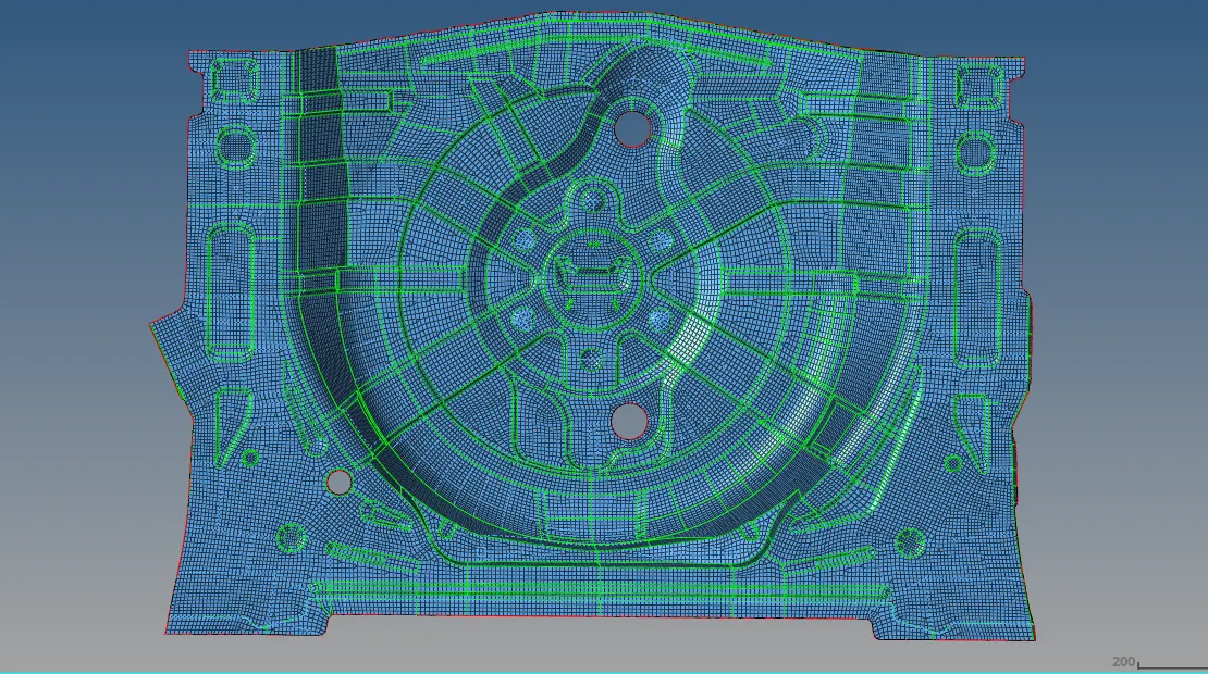
RESULT:
The given components mid surface was extracted and meshed accordingly to the given quality criteria
All features were captured properly