Tetra meshing of chasis assembly
AIM:
To 3d tetramesh the given component according to the following criteria
Mesh the components with an element size of 6 and maintain a tet-collapse of 0.15
THEORY:
Generally, 3d meshing is performed whenever the thickness of the components goes beyond 6mm or below 1/20 thickness area ratio. Few examples are like turbochargers, engine parts, intake manifolds, tyres, etc.3d meshing is generally done in two ways Tetra meshing and Hexa meshing. Generally, tetra meshing is preferred than Hexa meshing abiding to the complexities of Hexa meshing. In analysis perspective, 3d Hexa mesh will give better results than tetra mesh due to its better shape function.
Our main aim while performing 3d tetra meshing is to maintain the tet-collapse which is the distance from the opposite face divided by the area and multiplied by 1.24
PROCEDURE:
- At first, we import the model
- Here out of 8 components one half i.e the 4 geometries and other half are the mirror image models hence we can reflect by meshing one half of them
- We mesh each of the components by first performing necessary geometric cleanup
- Then we follow the method of 2d meshing with only trias and verify the quality of minimum and maximum element length
- We then proceed for the 3d tetra meshing and verify tet-collapse
- Tet collapse can be corrected manually or by using tetra remesh option by specifying the tetra meshing parameters
MODELS:
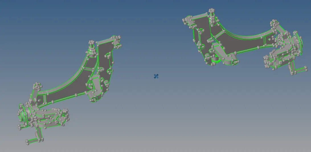
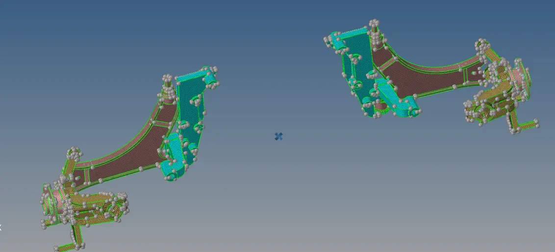
RESULTS:
- The components were 3d meshed according to the given criteria and tet-collapse was maintained
- Features were captured properly