Side impact test of a Dodge neon car with Pole
AIM:
Neon BIW side crash analysis as per FMVSS 214 standards
THEORY
Crashworthiness is the ability of a structure to protect its occupants during an impact. This is commonly tested when investigating the safety of aircraft and vehicles. Depending on the nature of the impact and the vehicle involved, different criteria are used to determine the crashworthiness of the structure. Crashworthiness may be assessed either prospectively, using computer models (e.g., LS-DYNA) or experiments, or retrospectively by analyzing crash outcomes. Several criteria are used to assess crashworthiness prospectively, including the deformation patterns of the vehicle structure, the acceleration experienced by the vehicle during an impact, and the probability of injury predicted by human body models. Injury probability is defined using criteria, which are mechanical parameters (e.g., force, acceleration, or deformation) that correlate with injury risk. A common injury criterion is the Head Impact Criterion(HIC). Crashworthiness is assessed retrospectively by analyzing injury risk in real-world crashes, often using regression or other statistical techniques to control for the myriad of confounders that are present in crashes.
Federal Motor Vehicle Safety Standards (FMVSS) 214 - Side Impact Protection
FMVSS 214, Side Impact Protection, specifies performance requirements for the protection of occupants in side impact crashes. The purpose of this standard is to reduce the risk of serious and fatal injury to occupants of passenger cars by specifying strength requirements for side doors. This standard applies to all passenger cars as well as 90% of light truck type vehicles with a GVWR < 10,000 lbs, manufactured on and after September 1, 1993, to August 31, 1994. On and after September 1, 1994, all light truck type vehicles with a GVWR < 10,000 lbs will be required to meet the static requirements.
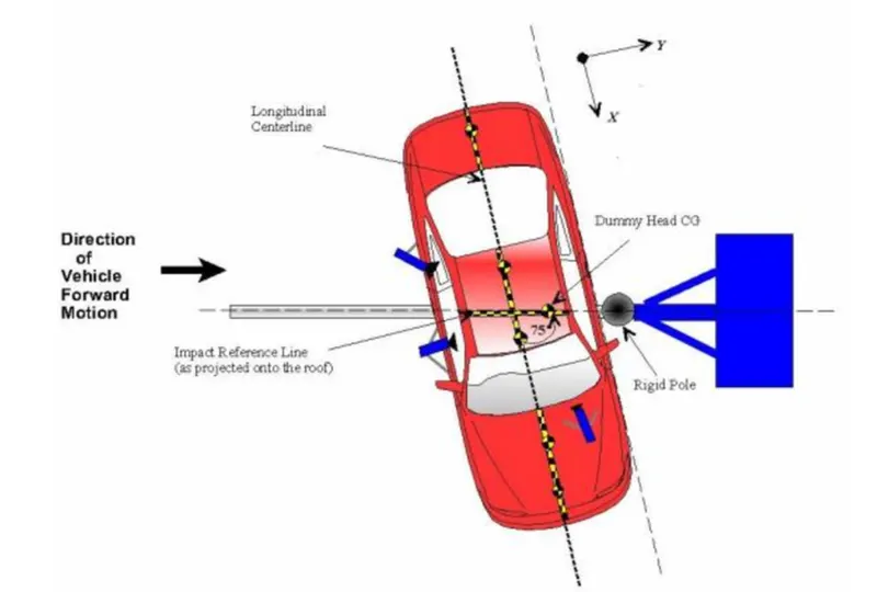
SIMULATION WORKFLOW

PROCEDURE:
I.Solver deck Setup
1. Import the 0000.rad file provided. Kg mm ms kN is taken as the units for this model. The .rad file contains the solver deck set-up for a reduced model of the Neon car. The Model has been reduced to only some essential parts in order to make it possible for the students to edit the deck in Hyperworks student edition which has a node limitation
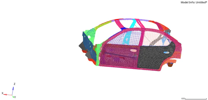
Reduced Neon car model
2. We have to check the unit systems to verify the unit consistency. This can be verified either using the radioss starter file or in begin cards in hypermesh
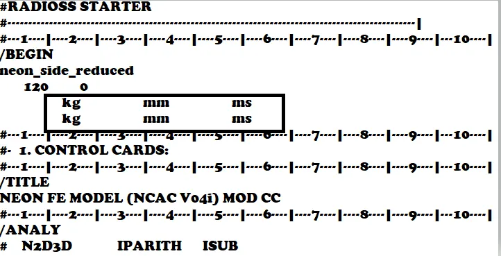
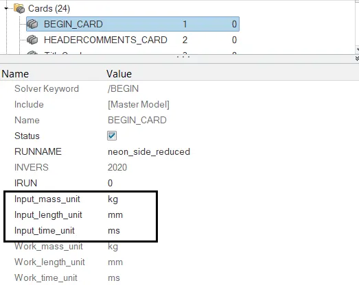
Radioss starter file Begin Card in hypermesh
3. We can also open the file in hypercrash and set the interface. Hypercrash too is a similar pre-processor like hypermesh but has a rather more friendly user interface.The deck already has some interfaces defined. We can delete these interfaces and set a single type 7 interface. We have to define the time history for the defined contacts to view the results in the output. Type 7 interface is a general type interface that can simulate impact between nodes and master surface
IMPORTANT INTERFACE PARAMETERS
lgap:-Determines how the size of the gap is calculated
Gap_min-Minimum Gap for activation
Inacti:- Action to take if initial penetration exists
lstf:-Action how the stiffness is calculated
St_min:-Minimum stifnnes used in the iterface
ldel:-What to do if elements and master segment fails
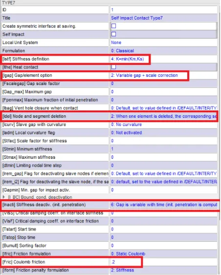
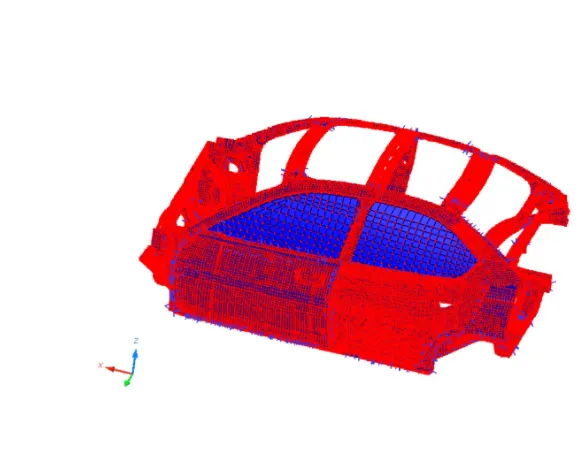
Type 7 interface parameters
4. Now we need to apply an initial velocity of 15.64mps which is equal to 35mph. The iitial velocity had applied to all parts of the body in the global y direction
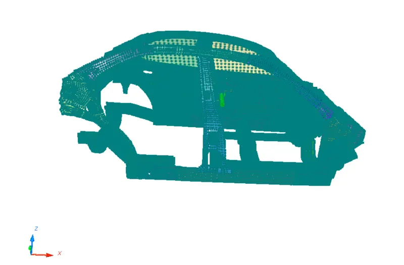
Initial Velocity setup in the global y direction
5. The Center of gravity(COG), also known as the center of mass, is that point at which a system or body behaves as if all its mass were centered at that point. Where the weight, and also all accelerative forces of acceleration, braking, and cornering act through it.
- Center of gravity location can be defined as:
- The balance point of an object
- The point through which a force will cause pure translation
- The point about which gravity moments are balanced
- The point which if the body is hanged from it will stay balanced (leveled as it is on the ground).
When analyzing the forces applied to the car, the CG is the point to place the car's weight, and the centrifugal forces when the car is turning or when accelerating or decelerating. Any force that acts through the CG does not tend to make the car rotate.
The center of mass height, relative to the track, determines load transfer, (related to, but not exactly weight transfer), from side to side and causes body lean. When tires of a vehicle provide a centripetal force to pull it around a turn, the momentum of the vehicle actuates load transfer in a direction going from the vehicle's current position to a point on a path tangent to the vehicle's path. This load transfer presents itself in the form of body lean. Body lean can be controlled by lowering the center of weight or widening the car track, it can also be controlled by the springs, anti-roll bars, or the roll center heights.A lower center of mass is a principal performance advantage of sports cars, compared to sedans and (especially) SUVs. Some cars have body panels made of lightweight materials partly for this reason.
Here we add mass to the model to make it a replica of the full car model and also bring the COG to the middle.It can be added through Load case-->Added Mass. Here we select Type 1 and add mas and bring the COG to the centre within the mass limit
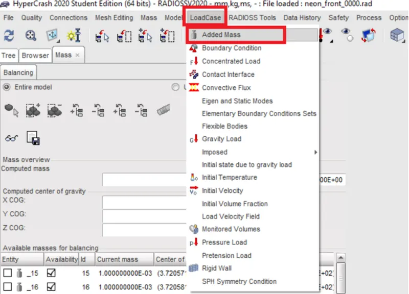
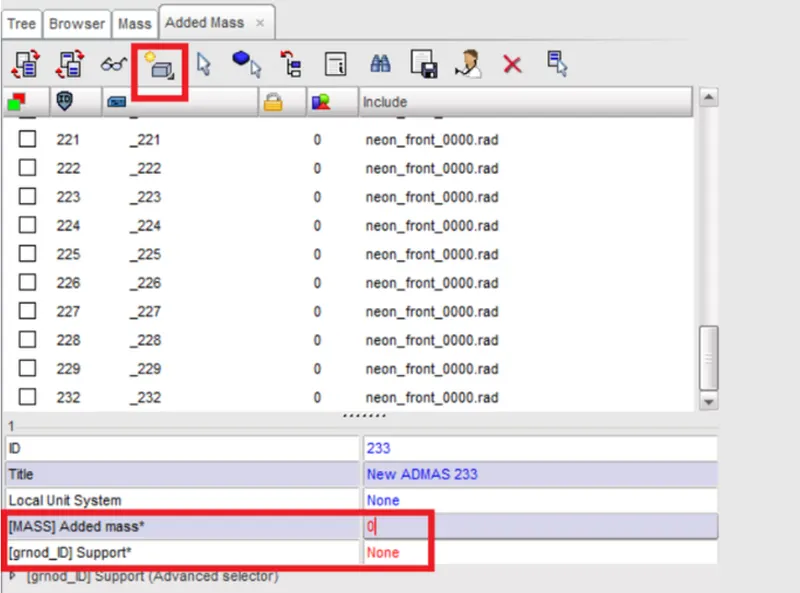
LoadCase-->Added Mass Added Mass-->Create New
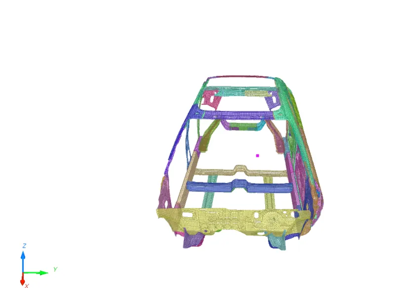
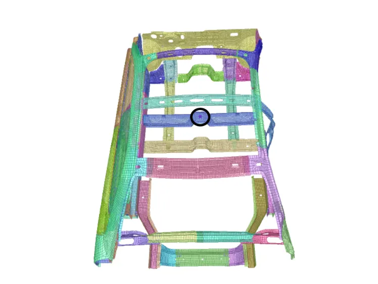
The initial cog of the given model Final COG of the model after mass addition
6. A cylindrical rigid wall is to be created for the car model to crash into. Rigid wall is created by specifying a base node and the axis direction of the cylinder. It is created with a co-efficient of friction as 0.1. The diameter of the rigid wall cylinder is taken from the FMVSS 214 Standards which is 254 mm.
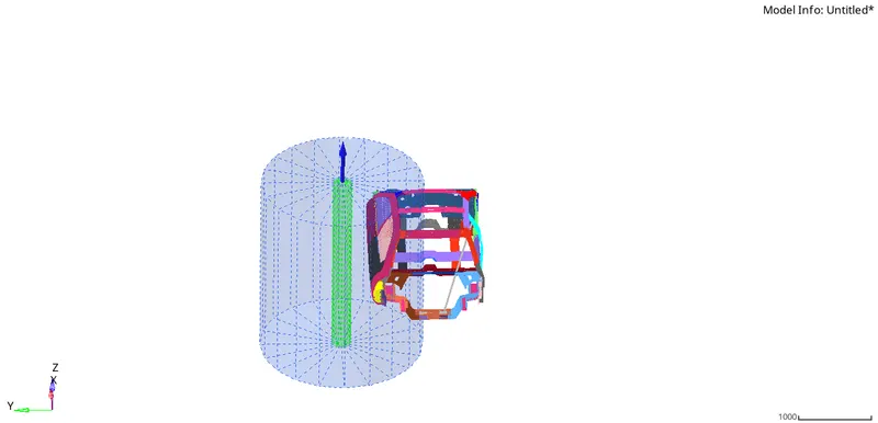
Rigid Wall Creation
7. For receiving sectional outputs of some parts we have to define sections there. Initially we create a frame Create-->Frame-->MOV and with respect to that we define a section Create-->SECT-->SECT . We then define its respective output blocks
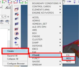
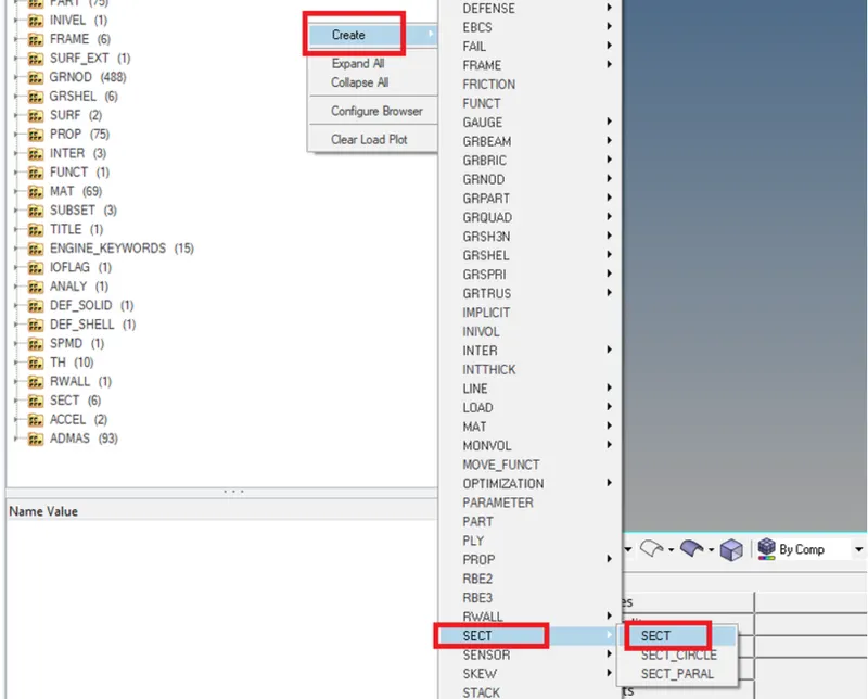
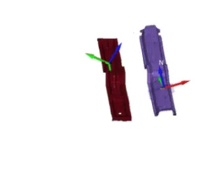
Creating a moving frame Creating a Section Sections defined
8. The nodes for which intrusions are to found are marked. To measure intrusions springs are set.Then they are assigned respective properties we give a very low stiffness so we can measure the intrusions on the nodes.One end of the spring will be on the nodes where intrusions are to be measured and the other end will be on a node that is free from any deformation during the crash .Node Id es for the Fuel Tank is 123239. Node Id 123281 defines for the 8-Pillar. Node Id 123254 defines for Hinge Pillar. Thereafter its respective output blocks are also defined
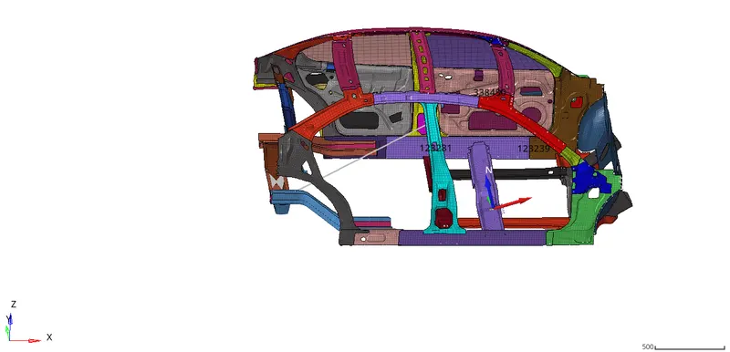
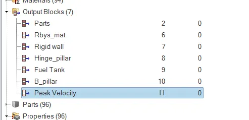
Nodes numbers highlighted where intrusions are to be found Output Block
9. We define the end time and time step as 80ms and 0.5 microsecond respectively. Stop time is set as 80ms in the Engine keywords-->RUN.To mention time step we go to ENGINE KEYWORDS-->DT-->DT/NODA
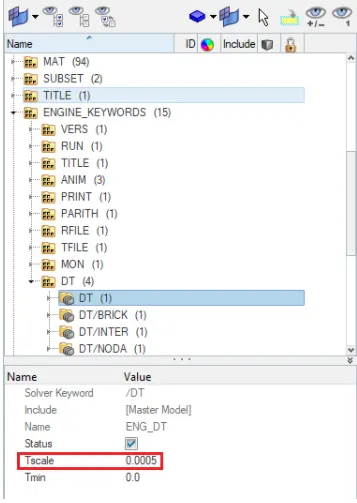
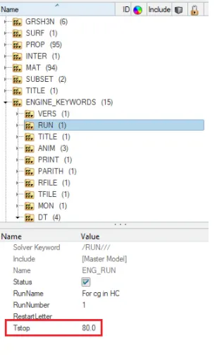
Time step is set as 0.5 microsecond or 0.0005ms End time is set as 80ms
II. MODEL CHECKER
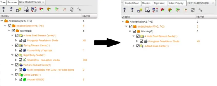
1. Now that we have setup the solver deck we need to check the model for any error.The connectivity of the model was checked to see if there was any free parts
2. The BIW model is checked for any initial penetrations or intersections in Hypercrash as it helps to detect errors more accurately than hypermesh. To check this, go to Penetration Check in Tools tab. The self contact interface created is selected for penetration check. Here all errors were corrected and we are only left with some warnings which can be ignored
RESULTS:
1. Now we have to run the analysis using Analysis-->Radioss-->Options-->-nt 4-->Radioss.The run is completed. After successful completion of the run open the radioss engine out file and check for errors. Mass error should lie within (1-3%)at the maximum and energy error should lie within (5 to -15%).We find that errors are well within the range. Hence here the results are acceptable. As the error is negative, it means that some energy has been dissipated.Now we move forward for post-processing of the results
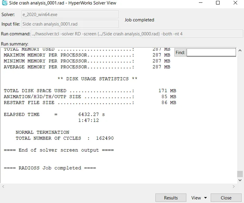
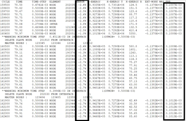
Output results
Now we can post-process our results using Hyperview and hypergraph. Hyperview helps to get useful animation contours and hypergraph helps to plot the required data
The simulation was run successfully. Here the mass error and energy errors are within acceptable ranges hence we proceed further.
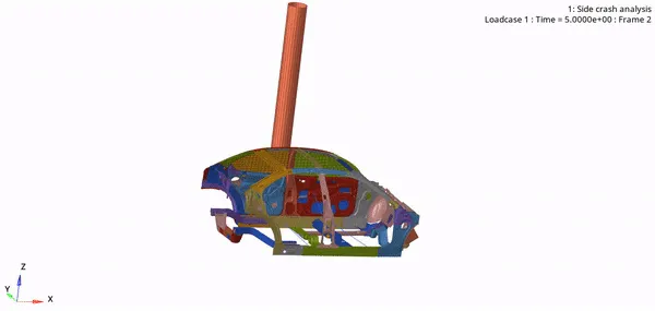
In the crash animation, we can see the left side deforming a lot more than the right side which is bound to happen here
Von mises stress
Von mises stress is very important in understanding the stresses that are acting upon BIW fixtures when car crash occurs. It is important for stress to flow from one component so that stresses can be absorbed by different car components so as to ensure maximum safety for passengers. The maximum von mises stress observed is 0.5216 GPa
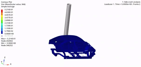
Von-mises stress contour
Energy Plots: The plot shows a decrease in Kinetic energy and an increase in Internal Energy after occurrence of impact.The total energy has been same throughout. The choice of proper element formulation has helped to keep hourglass energy to a very negligible value. The contact energy can be seen increasing across the run with an increase in deformation thus resulting in increase in contact
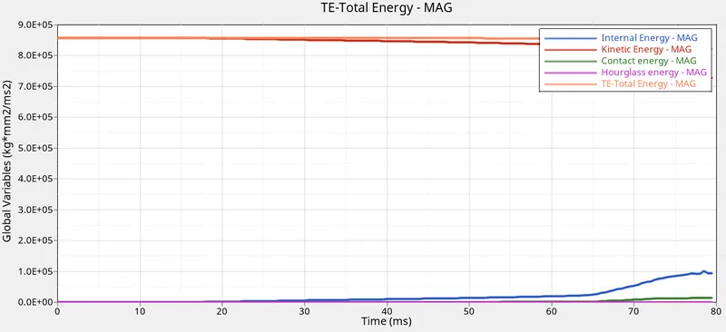
IE_KE_CE_HE_TE vs Time
The force increases with the impact and then reduces as time passes. The force experiences a maximum of ~1900 KN
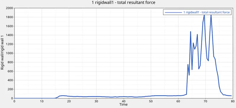
Rigid wall forces
Here we plot the intrusions of B-pillar , fuel tank and hinge. Intrusions are relative displacements of these nodes with respect to the nodes defined on the least deformed part. Intrusions were measured using nodes in the respective regions. The intrusions were calculated as 558.928mm, 224.17mm, and 146.17 mm for B pillar, hinge pillar, and fuel tank region, respectively. Velocity on node 337773 was also recorded.
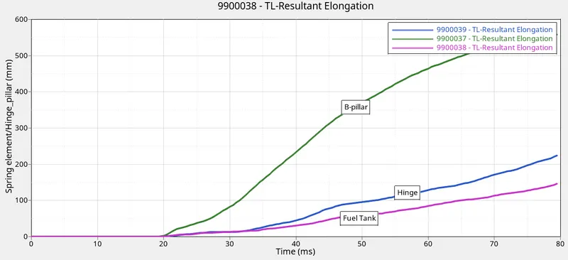
Hinge Pillar, Fuel Tank, B-pillar Intrusions
Here we can see one force member comparatively high with respect to other is due to the section being defined close to left side where much deformation occurs
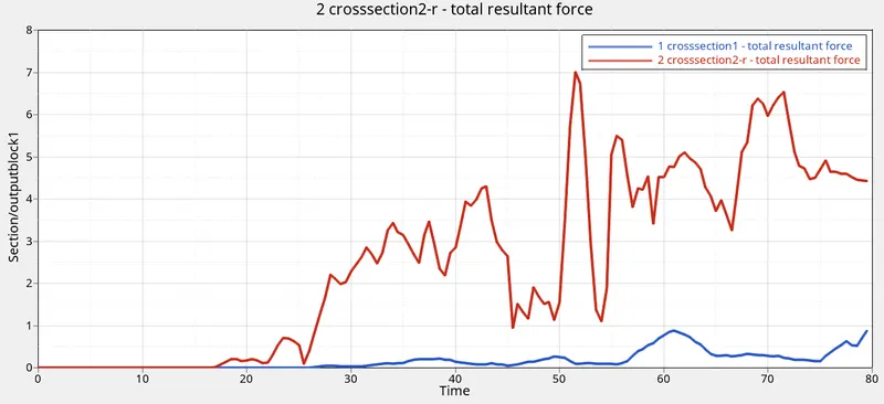
The sectional forces on the two cross members
The velocity was nearly constant till 18ms there undergoes several fluctuations and there is a decrease in velocity due to impact with the pole
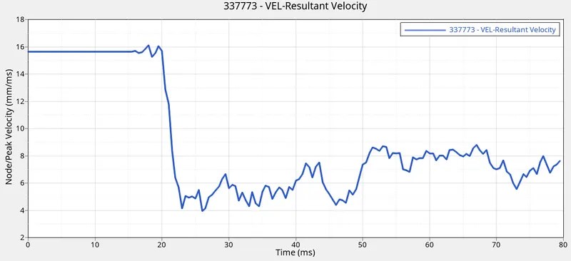
Velocity measured on the node 33773 the node on the door component
CONCLUSION:
i. The solver deck was set-up as per the instructions.
ii. All necessary output requests were placed.
iii. The simulation was run successfully with acceptable amounts of energy error(-2.7%) and mass error(0.01%).
iv. The sectional forces were plotted for both the cross members. The more sectional force was recorded on the cross member 1 compared to 2 which shows that cross member 1 transfers the majority of the force.
v. Intrusions were measured using nodes in the respective regions. The intrusions were calculated as 558.928mm, 224.17mm, and 146.17 mm for B pillar, hinge pillar, and fuel tank region, respectively. Velocity on node 337773 was also recorded.
vi. Thus, for increasing occupant safety, the cross members need to be made more robust. Also we can reduce the intrusion in the fuel tank by increasing the stiffness of the fuel tank and adding extra masses to it which can resist much deformation during crash
All simulation files can be seen here