Transient Simulation of Long Piston With Cam
AIM:
To perform a transient analysis on a piston and cam mechanism model with Frictionless contact, Frictional with 0.1 and 0.2 as the frictional contact for a total of 3 cases
INTRODUCTION
A Cam is a mechanical device used to transmit motion to a follower by direct contact. The driver is called the Cam and the driven member is called the follower. In a Cam-Follower pair, the Cam normally rotates while Follower may translate or oscillate. A familiar example is the crankshaft of an automobile engine, where the cams drive the push rods, where pushrods are followers to open and close the valves in synchronization with the motion of pistons. Design of Cam is difficult and tough job for a design engineer as each and every competitor in industry market always looks for the better performance of the mechanical system. So, a design engineer has to look for an objective mechanism. Also, it is important to look for better performance in actual loading conditions. With transient structural analysis we can get the idea and the behavior of the mechanism with different results such as deformation, stress , strain etc. with respect to time. A transient analysis, by definition, involves loads that are a function of time. You can perform a transient structural analysis (also called time-history analysis) in the Mechanical application using the transient structural analysis that specifically uses the ANSYS Mechanical APDL solver
PROCEDURE:
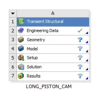
Open transient structural module into the workbench, drag and drop from the toolbox to the workspace
Open engineering data and add the required material for the simulation, here structural steel
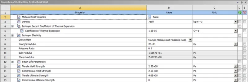
Material Definition
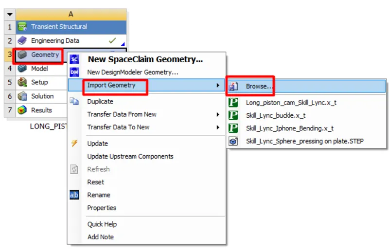
Import the geometry and Open in SpaceClaim to check the model for any abnormalities or defects
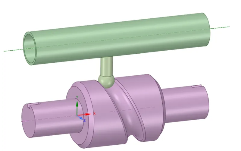
Open ansys mechanical module to set up the analysis and run the simulation. Rename the geometries as per our convenience for easy understanding.We set the stiffness behaviour of components of not our intrest to rigid, hence those would be considered as point masses at the centre of gravity
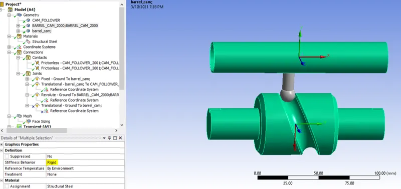
Stiffness behavior set to rigid
Now we move on to the connections. Here we set frictionless contacts in this case and frictional for the next two test cases with coefficient as 0.1 and 0.2 respectively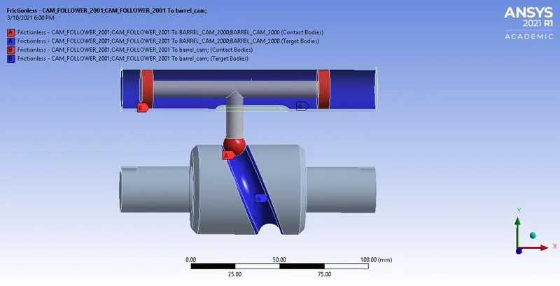
Contact Definition
Now we have to define the respective joints needed for the simulation
Joints: Joint_1
Connection Type: Body-Ground Type: Fixed Body: Barrel 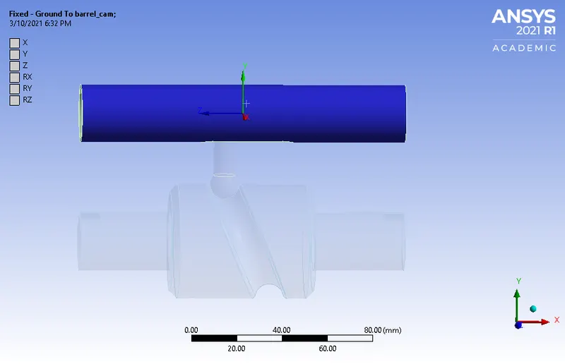
Joint_2
Connection Type: Body-Ground Type:
Revolute Body: Cam
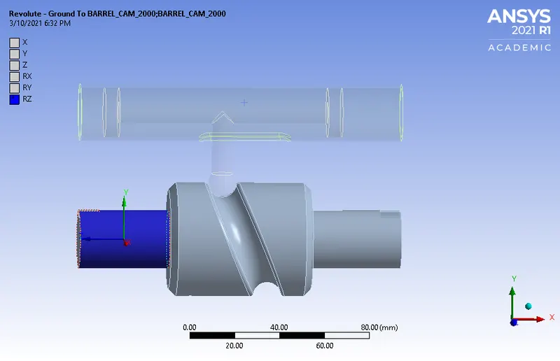
Joint 3
Connection _Type:Body-Ground
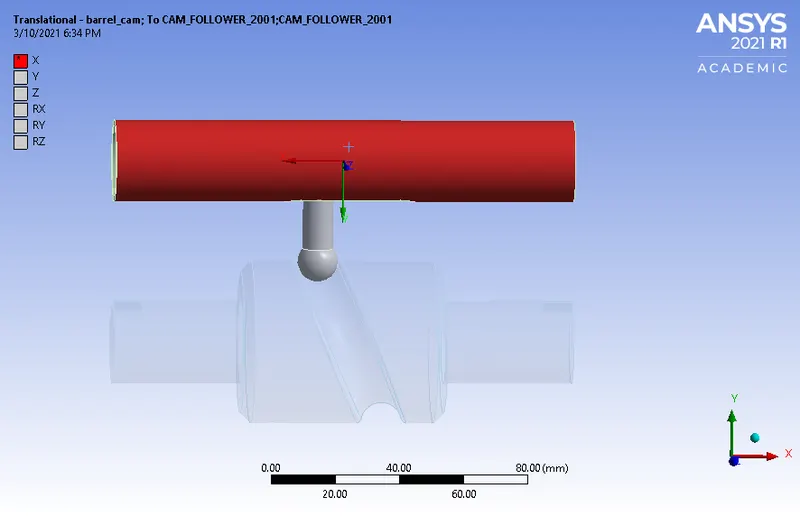
Type: Translational
Body:Follower
Meshing
Now we need to esh our model. Here the rigid bodies won't get meshed . We insert face sizing in the area here we need more accurate results. The component is meshed with a element size of 8mm and a face sizing of 3mm
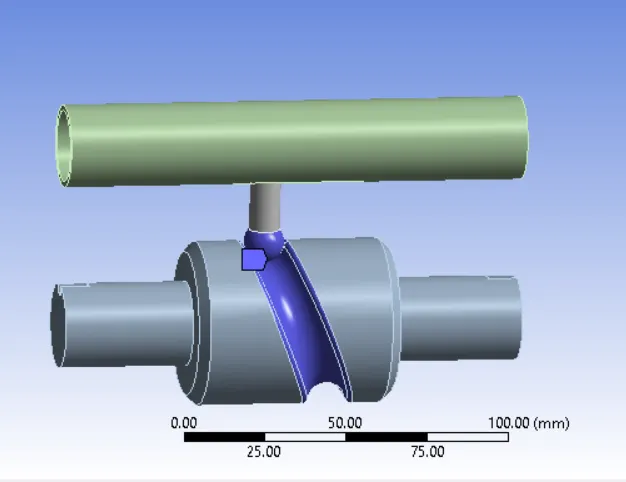
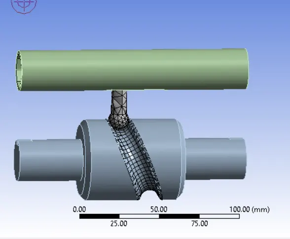
Face sizing of 3mm Meshed Component
• Analysis Setting
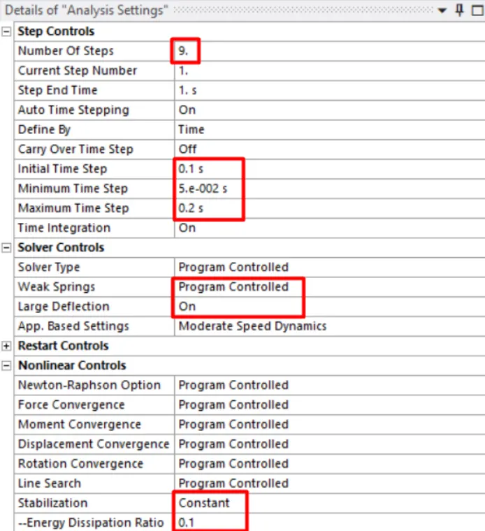
Following changes have been made to save computational time and ease convergence of solution. 1. Auto-time Stepping is enabled to proceed the solving in small time increment steps. 2. Weak Spring and Large Deflection options are also enabled to aid in solving. 3. Stabilization option is switched to constant and 0.1 is provided as Energy Dissipation ratio.
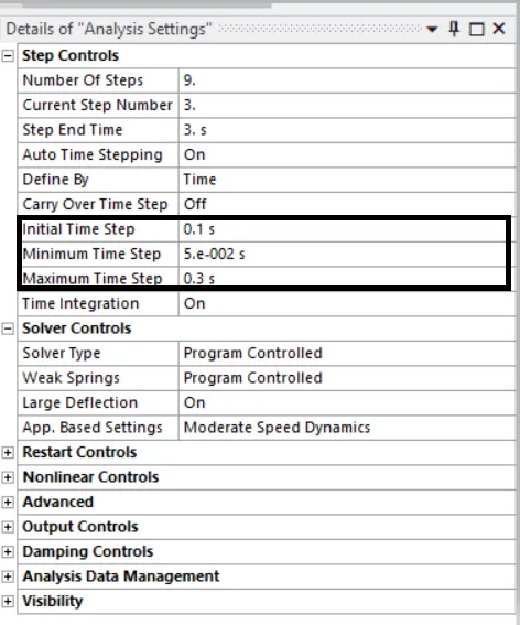
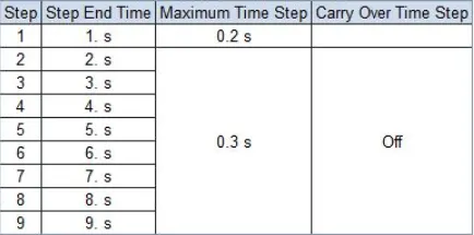
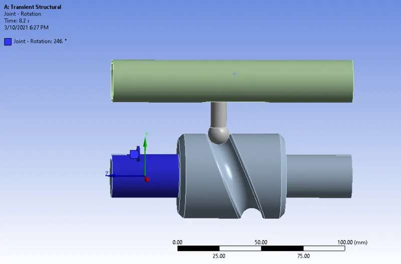
Now apply joint load as rotation in tabular data. We enter the rotation angles in tabular data from 0 to 270

• List the output required Equivalent Stress, Directional Deformation, and Equivalent Elastic Strain and run the simulation.
CASE-2
• Select the two contacts and change the contact type to frictional with a coefficient of friction of 0.1. • Setup the analysis as case-1 and simulate the model.
CASE-3
• Select the two contacts and change the contact type to frictional with a coefficient of friction of 0.2. • Setup the analysis as case-1 and simulate the model.
RESULTS:
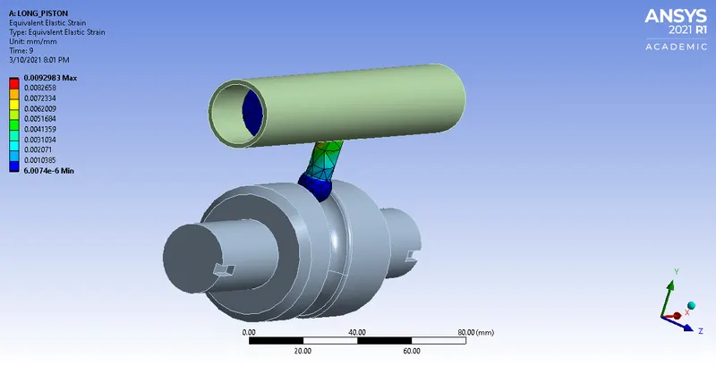
Equivalent Elastic Strain Contour
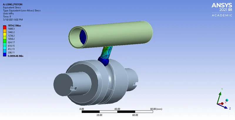
Equivalent Stress Contour
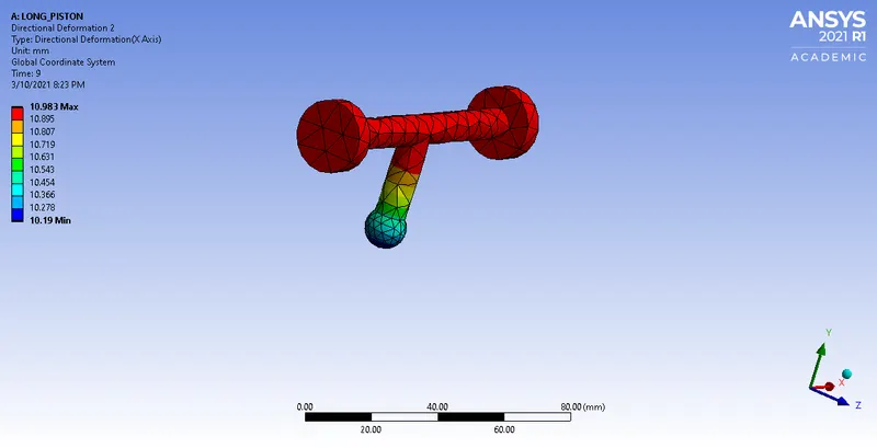
Directional Deformation Contour
CASE 2:Frictional Coefficient 0.1
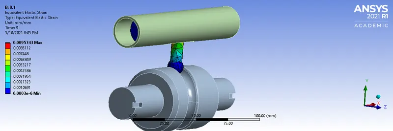
Equivalent Elastic Strain Contour
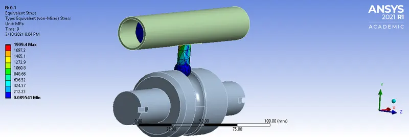
Equivalent Stress Contour
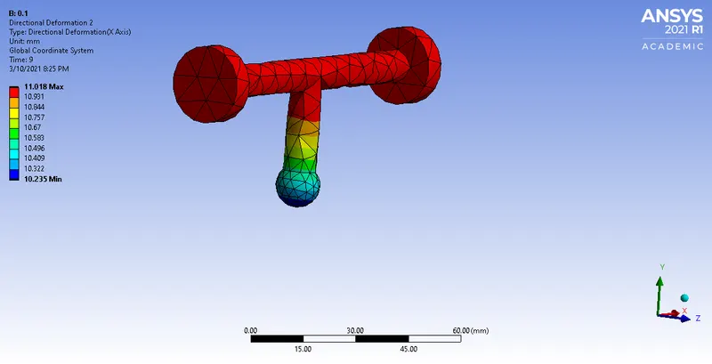
Directional Deformation Contour
CASE 3:FRICTIONAL COEFFICIENT 0.2
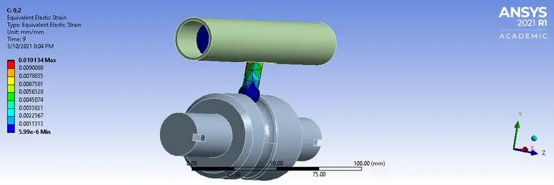
Equivalent Elastic Strain Contour
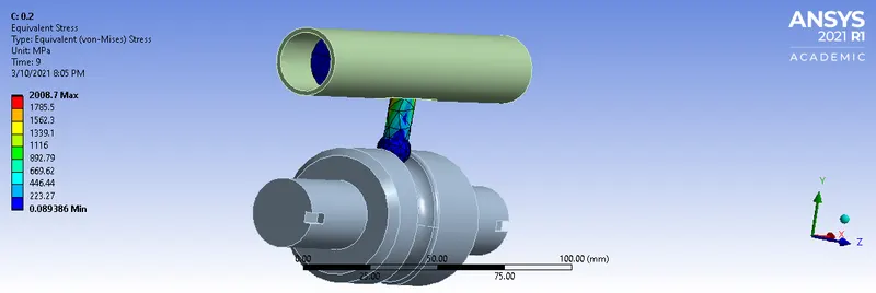
Equivalent Stress Contour
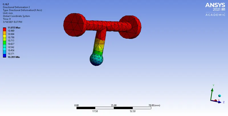
Direction Deformation Contour
CONCLUSION:
- The Long Piston With Cam simulation was setup and run successfully and required results were extracted and tabulated
S.No Directional Deformation Von mises stress Equivalent Elastic Strain 1 10.983 mm 1854.3 Mpa 0.0092 2 11.018 mm 1909.4 Mpa 0.0095 3 11.055 mm 2008.7 Mpa 0.0101 - As we know that it is never possible to have complete frictionless contact between cam and follower. So, minimum friction is desired for any mechanisms. As per results, we can observe that as the friction increases, stress and strain values increases and deformation due to higher pressure
- The equivalent stress and equivalent elastic strain incase of analysis with frictional contact are less compared to the equivalent stress and equivalent elastic strain in case of the analysis with frictional contact with a coefficient of friction of 0.1 and 0.2 because friction is the force resisting the relative motion between two contacting surfaces, Hence when we have a higher coefficient of friction the resistance to motion is reduces hence it develops more deformation this results in higher equivalent stress and strains.