Week - 4
- Implement control logic of a “washing machine” using Stateflow as per given sequence:
- If the power supply is available, the system gets activated
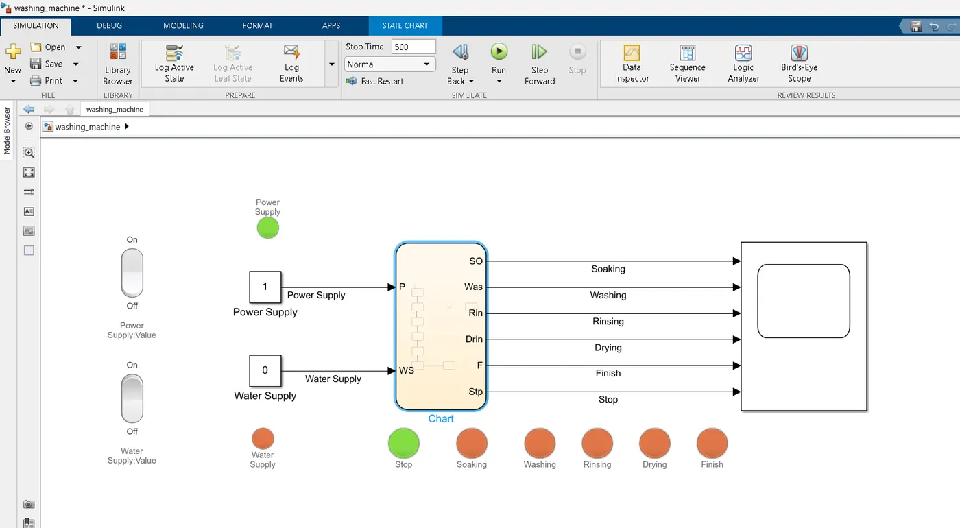
- If the Water supply is not available, stop the process & indicate through LED
- Soaking time should be 200s followed by Washing time of 100s.
- Then rinsing happens for next 20s & dryer runs for 50s
After all the processes have completed turn on the finished LED
-->
Step 1: Analysing the Input & Output from the given condition.
Here : Power supply & Watersupply are 2 main inputsources to run the programme.
Step 2: Control Flow logic:
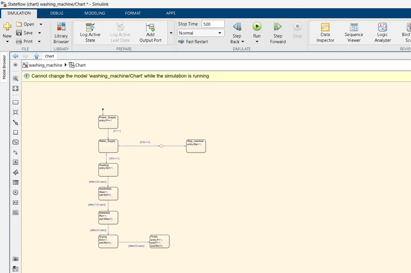
In the given example: MAchine is to be switched ON by Power supply, & then if the water is available it has to release the water which is also called as soaking cycle or else stop the machine indicating water not available.
Step 3: Following the 2 main conditions the process is then set based on given parameters.
Soaking for 200 sec,
washing for 100Sec,
Rinsing for 20Sec,&drying for next 50 sec.
After rinsing the finish LED glows indicating the process is finished.
Eg:1 Water Supply is Not Available.
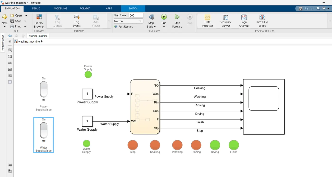
Eg: Power Supply & water supply available
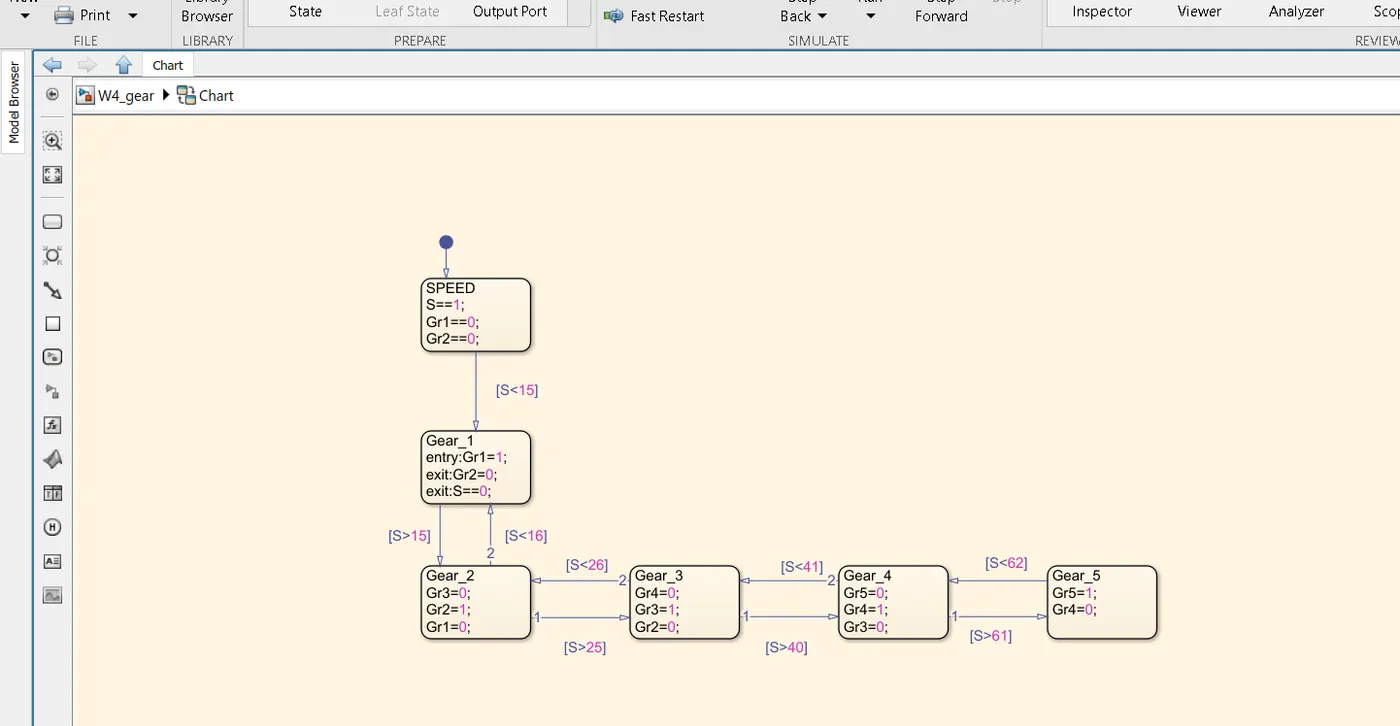
2. Make a Simulink chart for the “Gear shift” logic as per below conditions:
Speed Range(kmph) Gear
0 to 15 1
16 to 25 2
26 to 40 3
41 to 60 4
Above 61 5
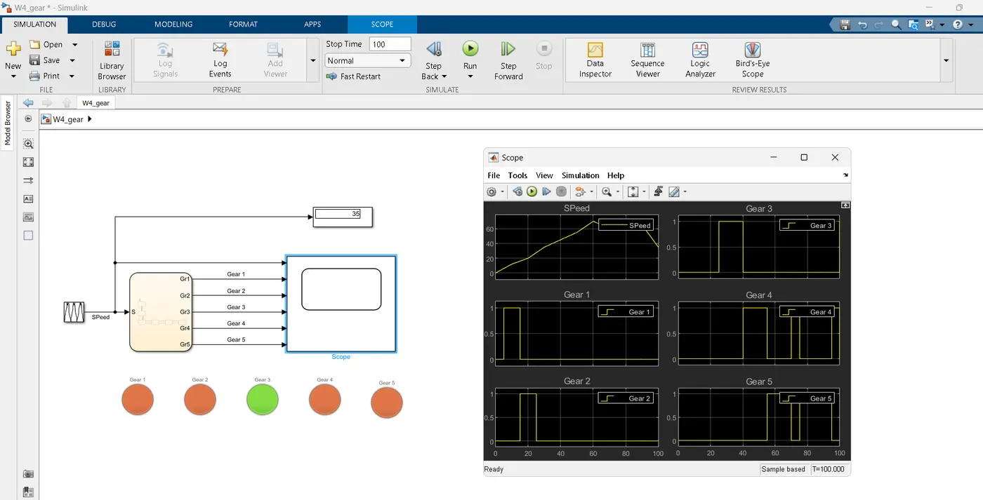
Give speed input while the simulation is running & display the gear number.
-->
Step1: Analyzing the input parameters & based on it creating Logic for the given condition.
Speed input :
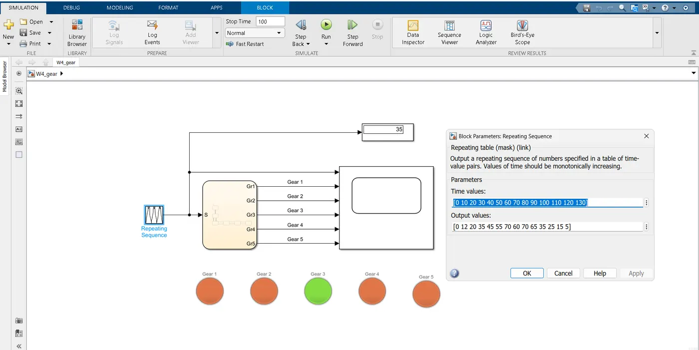
Step 2: Creating Flow graph based on given conditions. A gear steadily shifts Up & down depending upon speed parameters.
Step 3: Checking for Errors by compiling or running the document.
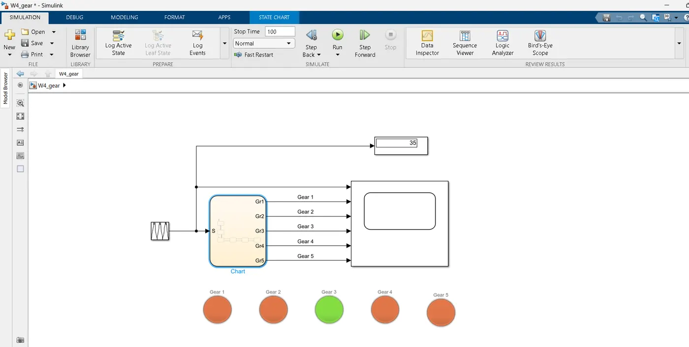
From the above image we have succesfully displayed the speed of the vehicle along with the required gear Shift.