Roof Design
Roof Study:
The Study of Roof is to Provide the given curvature , determine the weaker section if present and provide embosses on the outer roof section.Eg: Emboss creted on Roof of WaganR.
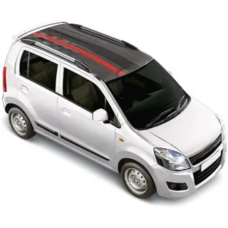
Purpose of Roof: Roof are made for different purpose namely , It covers the inside of automobile in rainy season /winter season/summer season. To make the roof stronger and for lonitivity the bow roofs , crntre roof rail and front and rear roof rail are manufacture.
The 2 main concers of roof is the distortion taking place in summer due to UV radiation , and dead weight acting on roof in winter season i.e in snow areas.
The Heat distortion Criteria: The criteria helps us in terms of how much the heats gets distorted , i.e the elasticity and ductility of material.During high temperature the outer roof shound not become ductile and form a permenant sag like section.Therefore we use heat distortion criteria.
W = [1.73 x 10^(-3) x L] + [1.85 x 10^(-8) x (R^2)/t] + [ 1.10x10^(-3) x l] - 2.68
Where,
L = Roof Length in X-Direction[mm](Roof dimension in 0-Y)
R = Roof curvature
R = 2(Rx*Ry)/(Rx+Ry)
Rx = X curvature (along the vertical axis)
Ry = Y curvature (along the horizontal axis)
t = Roof plate thickness [mm]
l = distance between Bow Roof [mm]
The heat distortion is calculated at 3y section i.e 300mm offset. Then offseting the line 100mm towards top and bottom. Then by using projection curve option the respsctive curves are projected on sketch and then used for creating the midpoint.Futher The vertical line is drawn through midpoint offsetting to 100mm to left and right direction. Refer the below attached Image.
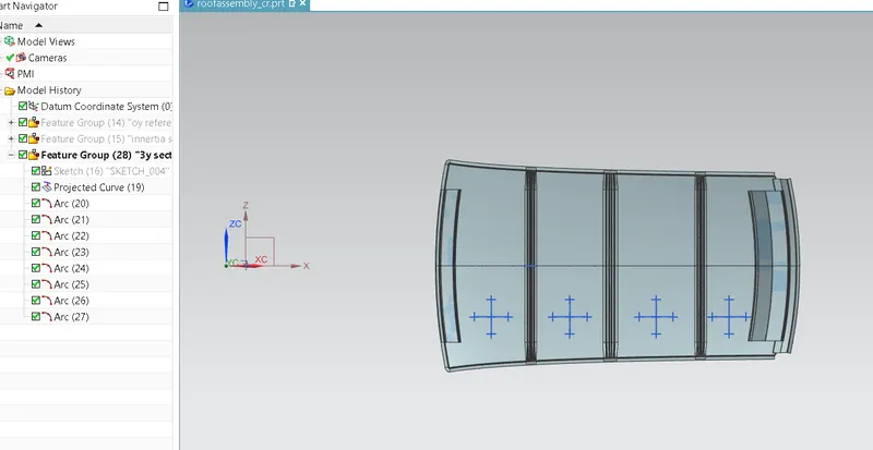
Calculation for same are listed below.
| Legends: | ||||||||||||
| Ly | c-c of rails (1st inner rail to 1st bow roof and so on) | |||||||||||
| y | cumulative distance (from inner rail to 1st bow roof , and from inner rail to center rail) | |||||||||||
| alfa | My * Lx2* 10-12 | |||||||||||
| My | Y(Ly-Y) | |||||||||||
| w=a*L+b*R^2/t+c*l-d | ||||||||||||
| Position | Rx | Ry | R | L | I | a | b | c | d | t | W | Judgement |
| Fr to 1Bow Roof | 5733.174 | 2647.02 | 3621.832 | 2085.78 | 408.8 | 0.00173 | 1.85E-08 | 0.0011 | 2.68 | 0.75 | 1.701648 | ok |
| Bow roof 1 to Centre bow roof | 4957.34 | 6257.63 | 5532.106 | 2085.78 | 390.16 | 0.00173 | 1.85E-08 | 0.0011 | 2.68 | 0.75 | 2.112479 | ok |
| Centre bow roof to 2nd bow roof | 3975.18 | 10592.83 | 5780.941 | 2085.78 | 453 | 0.00173 | 1.85E-08 | 0.0011 | 2.68 | 0.75 | 2.251042 | ok |
| 2nd bow roof to rear inner rail | 3321.61 | 14316.86 | 5392.194 | 2085.78 | 285.06 | 0.00173 | 1.85E-08 | 0.0011 | 2.68 | 0.75 | 1.959167 | ok |
The snow load Criteria:
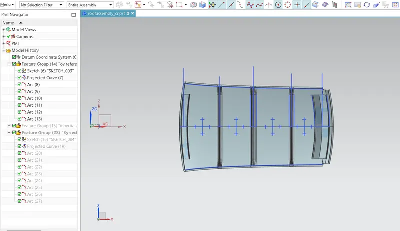
In colder region theres always an dead weight acting on the outer roof due to snow present on it , which is also called as dead weight.The main reason in calculating snow load is that the after removal of dead weight the roof must take its original position which depends on elasticity of the material.The snow load is calculated at 0Y section.
| Qr= Iy * t^2/(alfa*s*r^2 *b) | ||||||||||||||||
| Position | Rx | Ry | Ly | Y | Lx | L1 | L2 | S | Iy(mm4) | My | alfa | b | t | r | Qr | Judgement |
| 1Bow Roof | 4497.93 | 2647.93 | 1924.5 | 500.5 | 1146.9 | 500.5 | 468.5 | 484.5 | 1098.6 | 712712 | 0.937487 | 0.00000001 | 0.75 | 3572.93 | 10.65747 | ok |
| Centre bow roof | 3767.26 | 6167.83 | 1924.5 | 969 | 1096.7 | 468.5 | 531.4 | 499.95 | 2723 | 925879.5 | 1.113602 | 0.00000001 | 0.75 | 4967.545 | 11.14884 | ok |
| 2nd bow roof | 4276.66 | 11095.55 | 1924.5 | 1500.4 | 1068.7 | 531.4 | 424.1 | 477.75 | 1196 | 636319.6 | 0.726753 | 0.00000001 | 0.75 | 7686.105 | 3.279846 | ok |
| 2nd bow roof to rear inner rail | 4050.45 | 16132.82 | 1924.5 | 1924.5 | 1055 | 424.1 | 0 | |||||||||
Qr = [Iy x t2] / [α x s x [(Rx + Ry)/2]2 x 10-8]
Note: The Qr value given over here is correct.
Where,
α = My x Lx2 x 10-12 , My = Y(Ly-Y)
t = Roof plate thickness [mm]
Ly = Distance between the front and rear roof Rails on the Vehicle along with 0Y[mm]
Length of Roof panel with the center point between Roof rail Front /Rear as the front and rear reference point.
Lx = Distance between the Left and Right end of the roof on the Roof BOW [mm]
The width of the roof panel is exposed on the surface.
Y = Distance front Front Roof Rail to Roof BOW[mm]
s = Distance for which Roof BOW bears divided load [mm]
s = L1/2 + L2/2
Iy = Geometrical moment of inertia of Roof BOW (Y cross-section )[mm4]
Rx = Lateral direction curvature radius of roof panel Y cross-section on Roof BOW [mm]
Roof panel curvature Radius of the Length Lx in Front view
Ry = Longitudinal Direction curvature radius of the Roof panel X cross-section on Roof BOW [mm]
Roof panel X curvature radius of length s in Side view.
Apart From above 2 reasons , The roof must also be placed 80mm above the head of an average person which is also called as head room criiteria. , and should also follow the visibility criteria..
Conclusion regarding snow Load Criteria:
Form the above calculations , since the the S valve is greater then (250 ≤ s ≤ 380 we either need to either
-increase the thickness of bow roof.
- increase the width of the bow roofs.
-Add an another 3rd bow roof for the case.so distance automatically reduces.
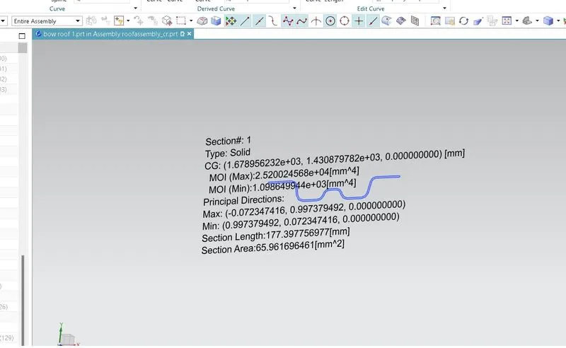
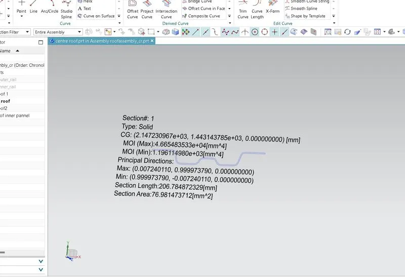
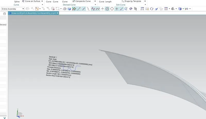
MOI has been attached below.
MOI is calculated to strength the weaker section along the body . It basic terms MOI is rotation of object from the axis of rotation where the whole mass is suppose tto be concentrated without changing its axis of rotation.
1. BOW ROOF 1
2. CENTRE ROOF RAIL.
3. 2nd BOW ROOF
Draft Analysis:
Draft analysis is done for the tooling section.Whether the part to e produced can be easily manufacture or not is provided by the draft analysis. The Draft analysis gives idea abouthow easily the part can be removed from dies.Given below are reults of each part.NOTE: MInimum of 7 Degree draft angle is necessary to easily remove the part from the dies, for smmoter operation.
1.Inner front rail
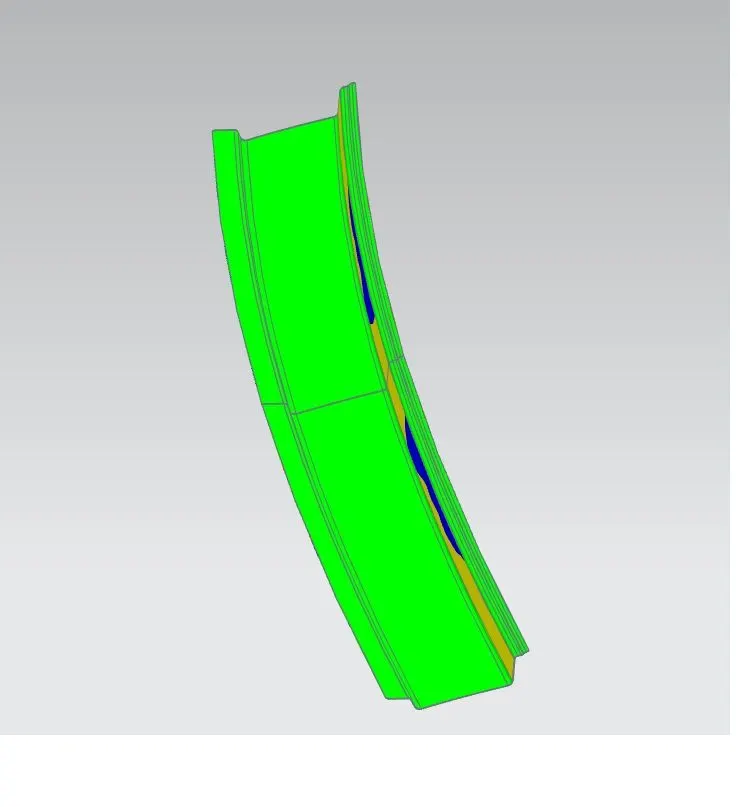
2.1St bow Roof
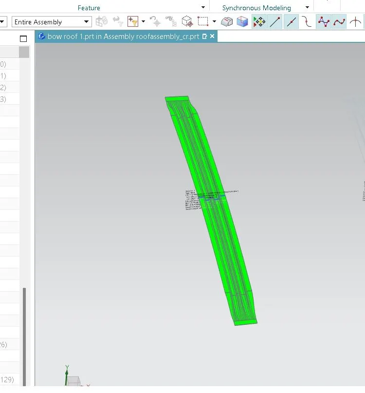
3.Center inner rail
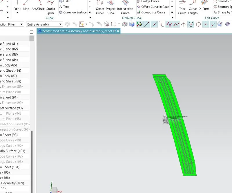
4. 2nd Bow roof
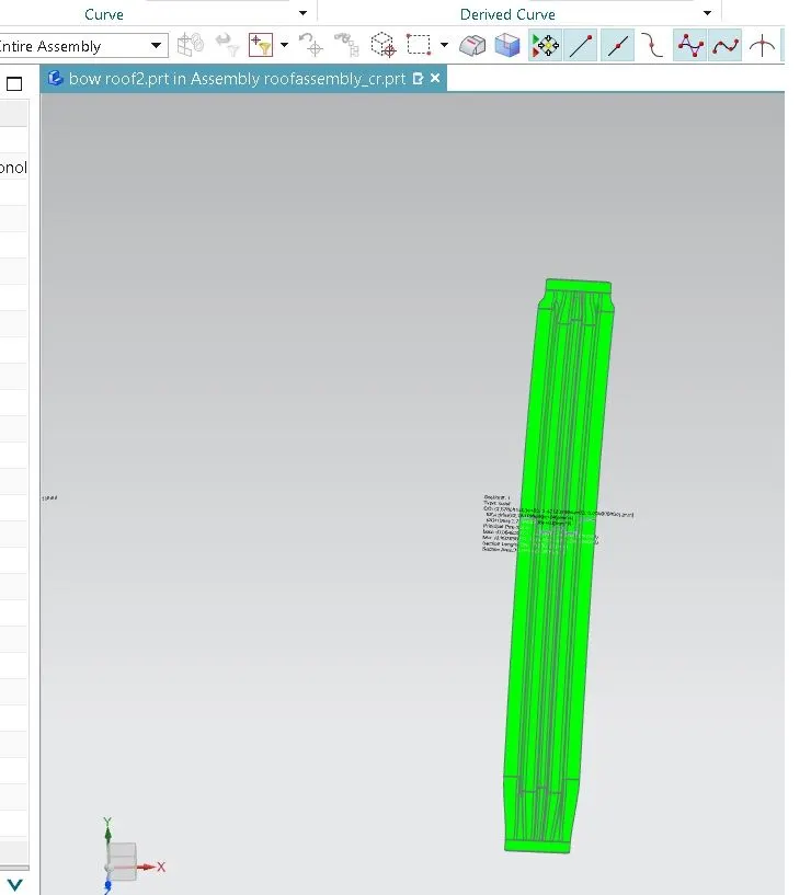
5.Rear Inner rail
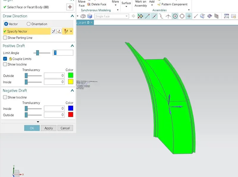
6.Outer pannel.
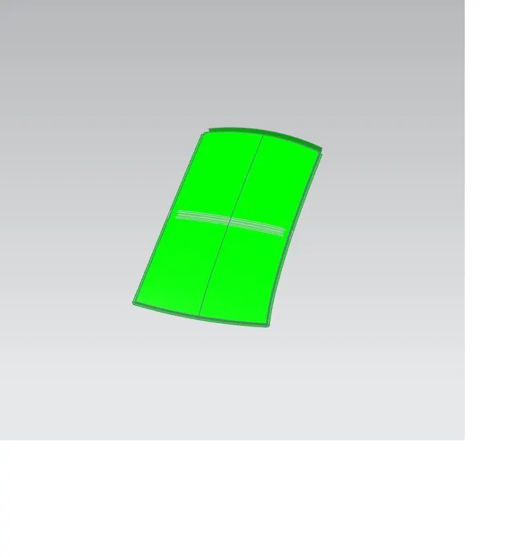
Views of the part:
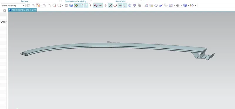
1.Front View
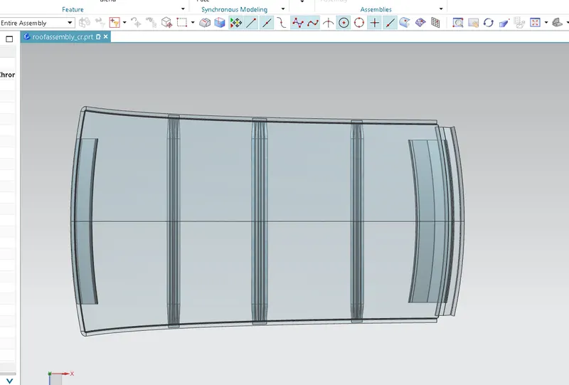
2. Top View
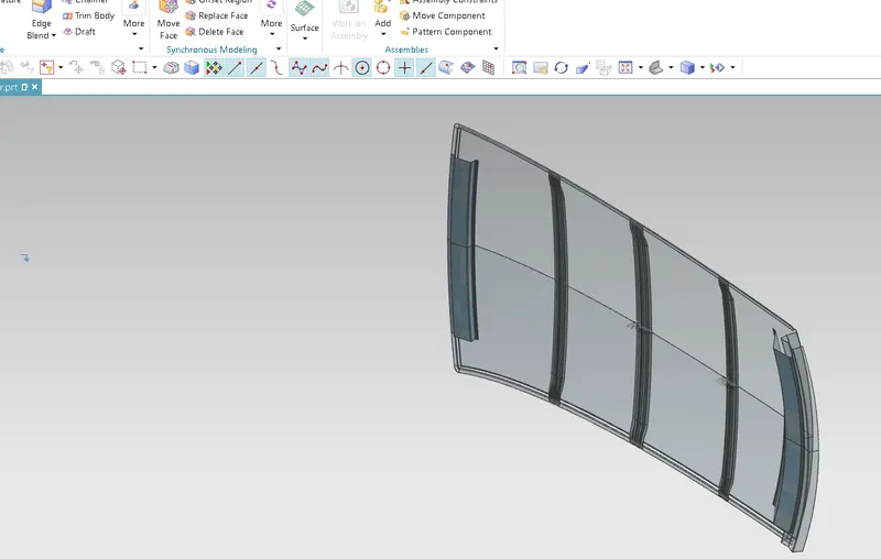
3. 3d view
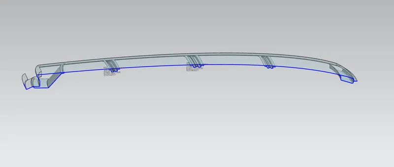
4. Section View.
Manufactring techniques used in roof design.
Stamping Process: The foremost used process in design is the stamping process. The sheet metal generally (0.4 to 6mm thk) is passed through a high tonne press /Bending M/C twhich then deforms into its shape of cavity.he press, a tool and die surface form the metal into the desired shape. Punching, blanking, bending, coining, embossing, and flanging are all stamping techniques used to shape the metal.