Week 9:- 2D Detailing Challenge
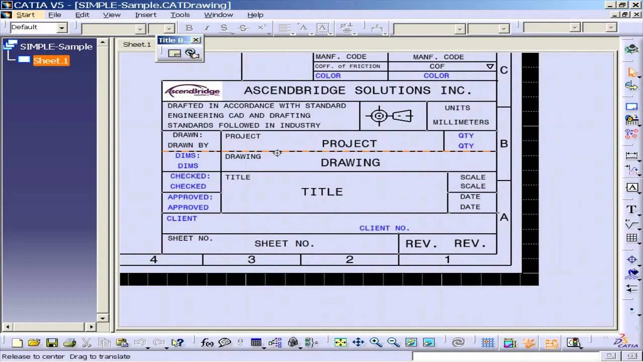
| What are the Drawing templates? |
-->
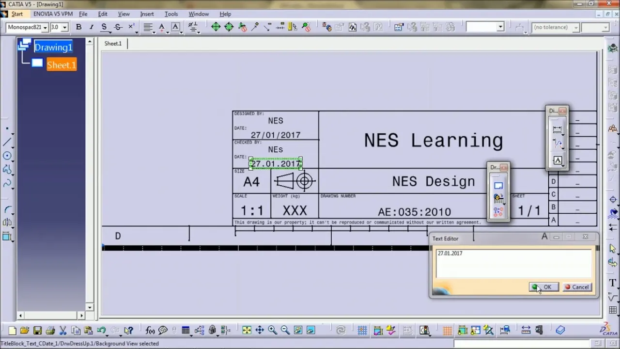
*Drawing templates are basically the drawing std as per customer requirment.
*Drawing templates are format that are used for detailing of different parts or units of the fixture
*There are n no. of details, that are readily available on template & are useful for various manufacturinng process, such as machining, Tolerance, surface treatments, name of parts , etc.
*Drawing templates also give information regarding the projection used, Scale of part or units etc.
| What do you understand by Angle of projection? |
-->
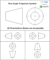
*ANgle of projection generally refers with the observer view side . In an automobile industry 2 types of projections are used 1st angle & 3rd angle.
*This angle of projections are basically views format of orthogonal views of assemblies or part.
*Angle of projection provides information of views in 2D detailing which helps in shhop floor machining & quality checking.
| What is the First angle & Third angle projection? and why can't we use the 2nd and 4th angle of projection? |
-->
-1st angle projection:
*In this projection the object is located in 1st quadrant.
*The plane of projection is considered behind the object.
*i.e top view is always at bottom, LHSV is always indicated on right side in 2d detailing.
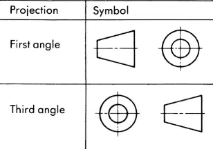
-3rd angle projection.
*In this projection, the object is considered to be in 3rd quadrant.
*The plane of projection lies inbetween the observer & part or component.
*i.e Top view is always on top, LHSV is always on left side in 2d detailing.
-*We dont use 2nd & 4th angle projection because Front & top views overlap, when the horizontal plane is rotated to 90 degres in clockwise direction.
| What is GD&T? What are the benefits of GD&T? |
GD& T stands for geometric design & tolerance .It is language of symbols & Standards used by engineers for easy manufacturing of the component. GD&T improves communication to machine shop by just providing symbols.
Benifits of GD&T:
*Standerdized design language
*A clear & precise way for customers, suppliers & production team to communicate.
*A method of calculation worse case mating limits
*Assembly is assured from qualified productin parts.
| Explain all the symbols used in GD&T? |
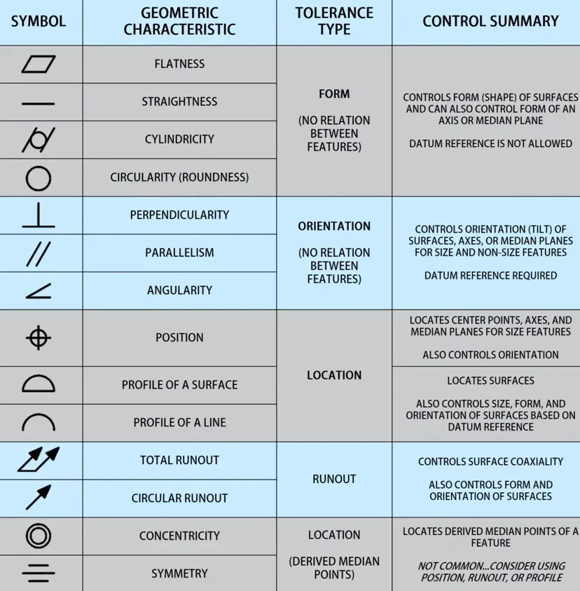
Generally there are 14 major types of GD&T used.These symbols are placed in the 1st compartment of feature control frames & defined the type of tolerance that is to be applied to the feature.
GD&T are categorised into 5 major categories FORM, Orientation, Location ,Run out & Location.
TYPE of tolerance
FORM: It consists of Flatness, straightness, cylindricity, Circularity.It controls the shape of the surface & can also control form of an axis or midian plane. DATUM Reference not required.
ORIENTATION:IT consists of angularity,perpendicularity, parallesim.It controls orientation of the surface,axes,or median planes for size & non size features. DATUM surface required.
POSITION: It consists of position, profile of surface, profile of line. It controls centre point,axes & median planes for size features.It also locates surfaces & controls size, form, orientation of surface based on datum.
RUNOUT: Total Runout & Circular runout. Controls surface coaxialy .Also controls form & orientation of the surface.
Location: COncentricity & Symmetry. It locates derived median points of the feature.