Advanced Sheet Metal Design Using NX Cad Challenge_1_Casing Design
TITLE: Design of Casing
Objective: To design a sheet metal casing model using advanced sheet metal operations.
Introduction: Sheet metal is formed into thin, flat pieces usually by an industrial process. Sheet metal generally have low weight-to-density ratio therefore they are been used in the automobile sector i.e light in weight with high strength is the property of steel. Depending upon the sheet thickness they are been classified into foil, sheet & plate . Foil ranging thickness from 0 to 0.4mm , Sheet from 0.4 to 6mm , & plate for thickness above 6mm. Sheet metal are been used for many applications in housewares utensils ,airplane, automobiles,decorative etc. Sheet metal design is done using various software such as solidworks, Catia , NX-Cad, creo etc.
Design methodology / approach:
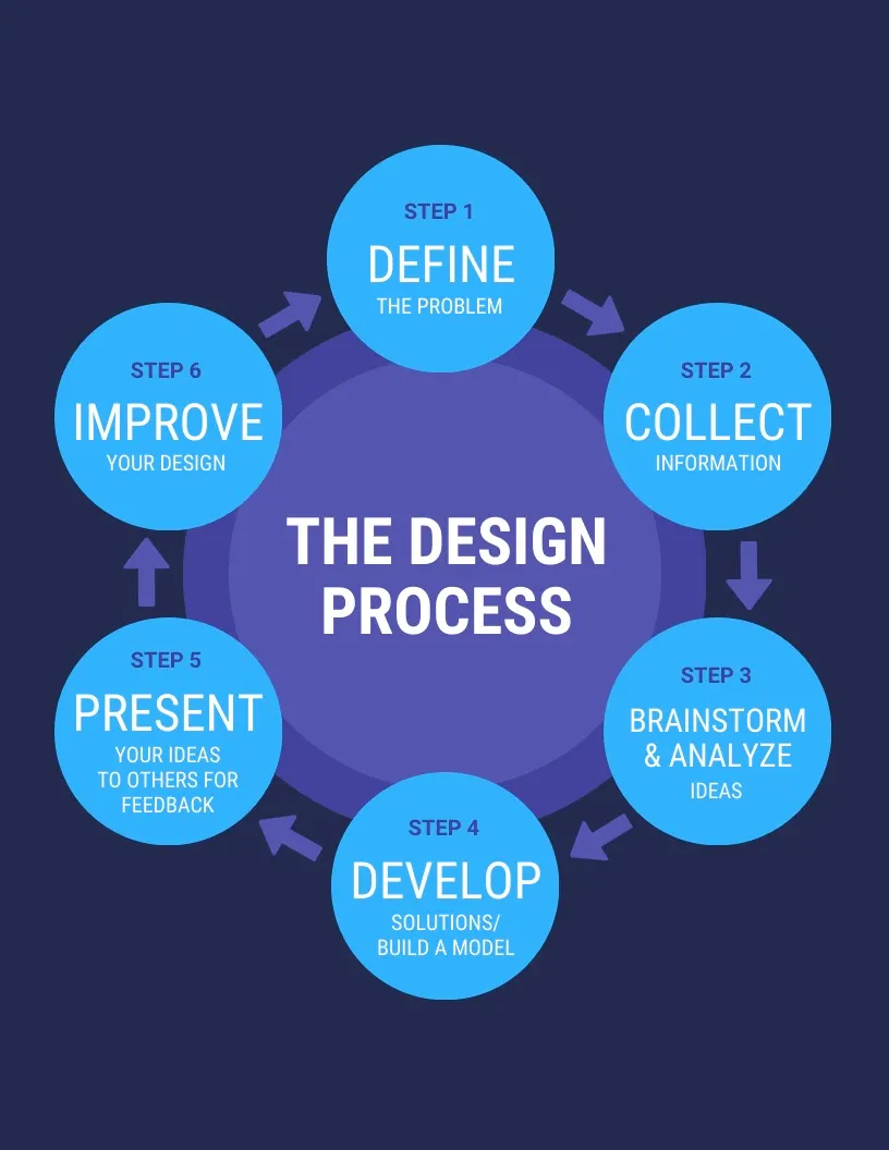
Define: The 1st step is to define a problem a problem for which a design is to be made.
Information: The next step is to collect information regarding the product for which the part is to be designed.
Brain Storming and analyze: Collection of ideas, arranging CFT meeting, approaching manufacturing production as per design requirements etc.
Development: Development of model in 3D cad software to ensure that the design meets the customer requirements.
Present: Present of the final model with ideas & approach as discussed in brain storming session.
Improve(feedback): after presenting, there might or might not be any improvement required in the product. After review of final design a pilot production is produced to ensure the proper fuctanality of the product that has been developed.
Design methodology for part in software:
1. Creation of file & saving in a particular location
2. Sketch of part in proper units and dimensions
3. creation of base tab as a sheet metal part as per thickness.
4. Creating Cut out as per requirement
5. Adding Additional features such as flanges , beads , hems etc
6. Drafting.
Description (Need to explain tools/ Features used while designing):
Tools used
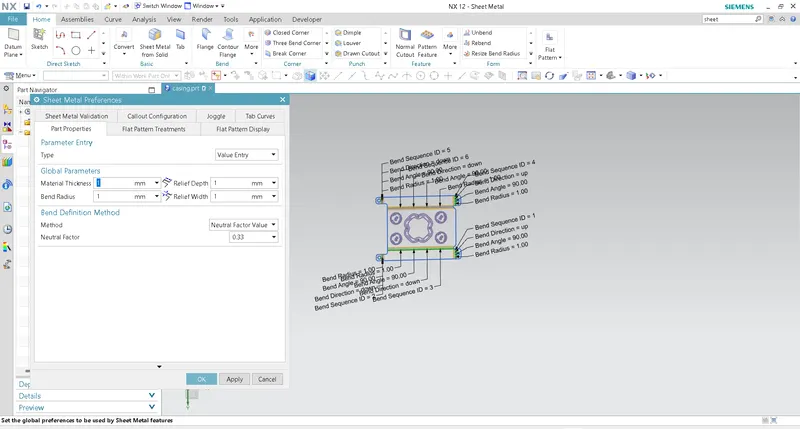
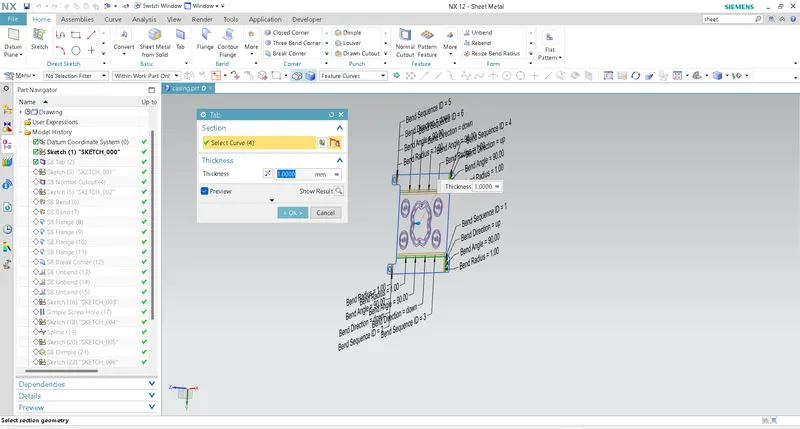
Tabs: Tabs are required to create the base feature. The thickness of the tab depends upon the input given at the start of the design.
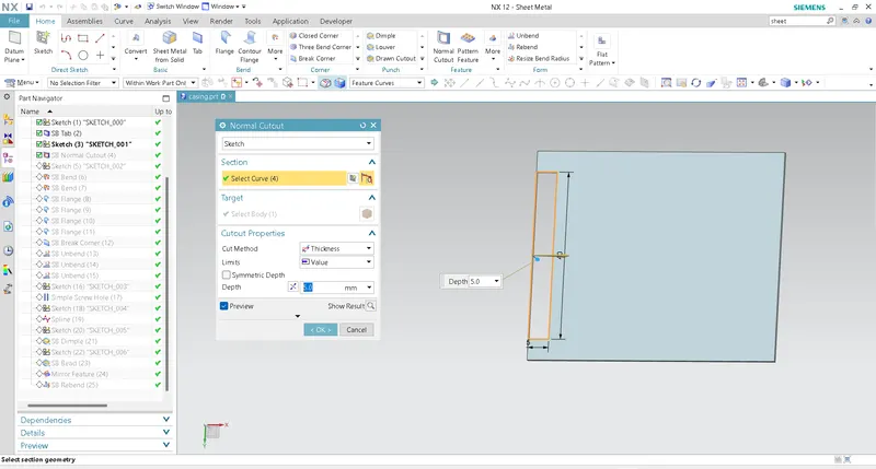
Cut:
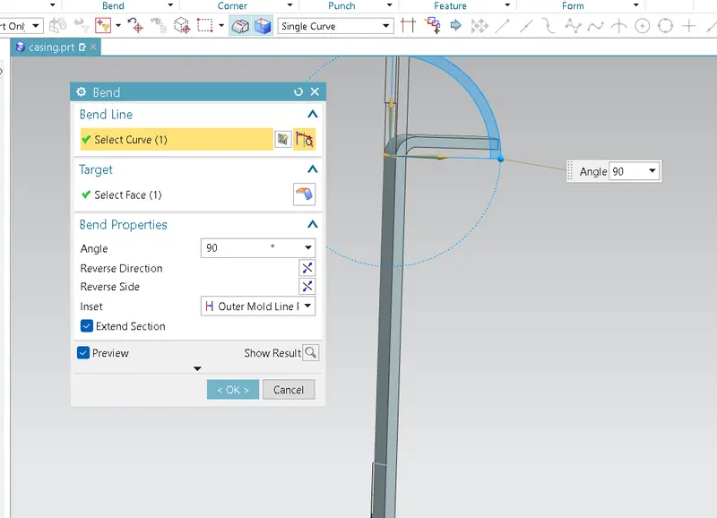
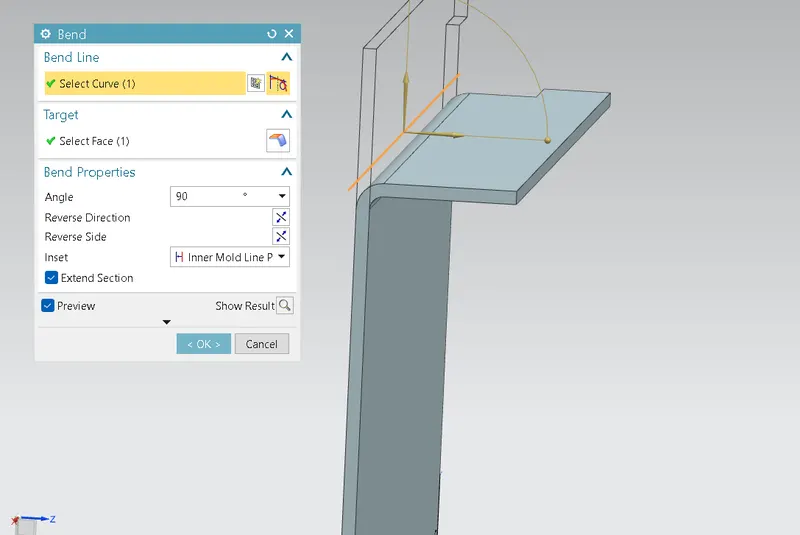
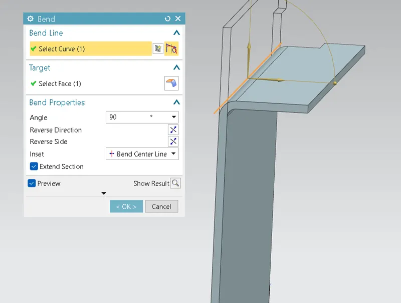
Bends: To provide proper mounting points and stiffness we use bends. Bends are characterized as follows
outer mold line: The flange is created from the stating point of bend an the entire flange is present outside the line drawn as shown in the figure.
inner mold line : The entire flange is inside the line drawn, i.e the line acts as the end point of the turning radius.
Bend center line: The bend line is perfectly at the center of the material to be bent.
Material inside: Unlike the inner mold line, the entire flange thickness lies inside the line.
Material outside: Unlike the outer mold line, the entire flange thickness lies outside the line.
Flanges:Flanges are used to connect the parts.
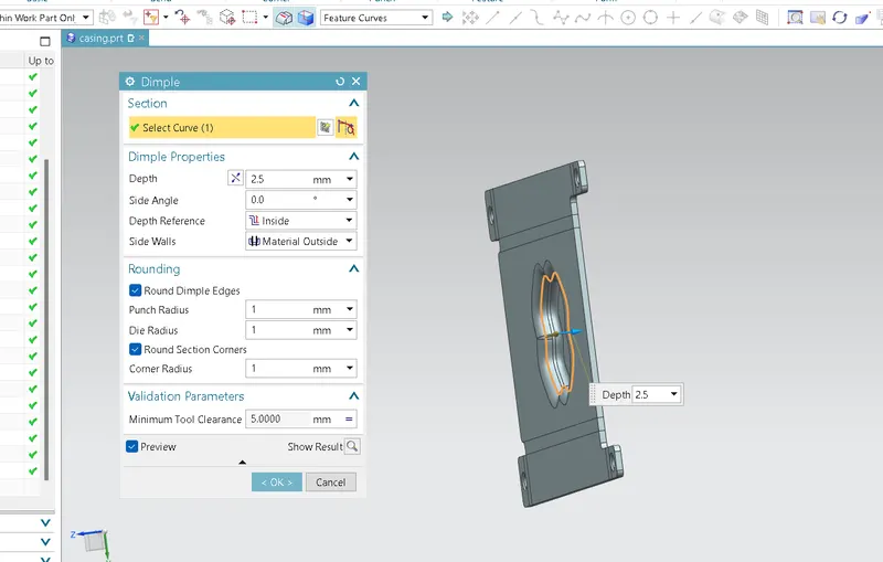
Dimple: Dimples are used to reduce the weight of sheet metal and improve the outer appearance of the part.
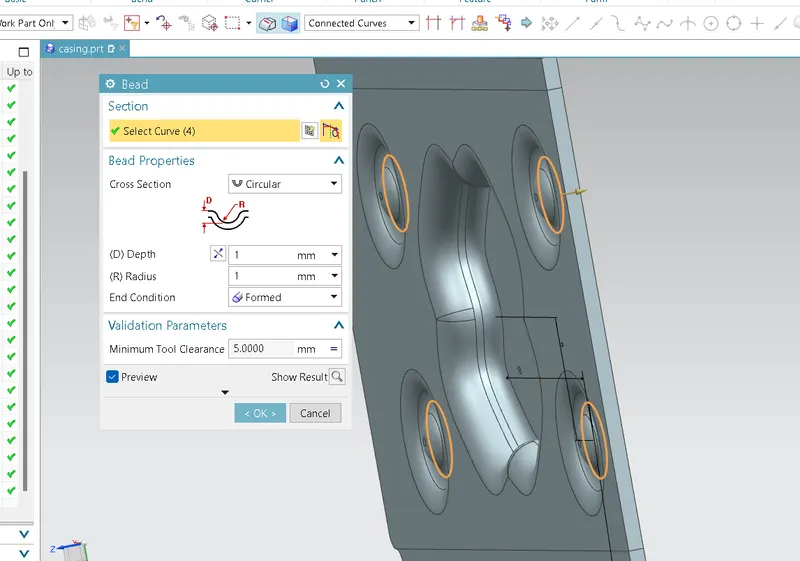
Beads: Beads are provided to increase the strength of the material.
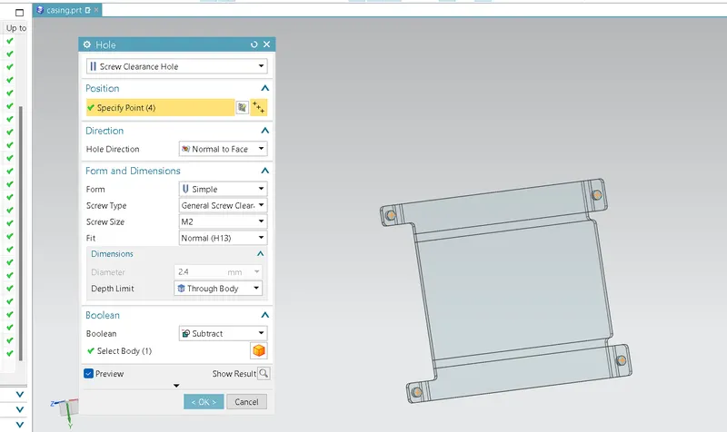
Holes: They are provided as per requirement to attached to another part . Holes can be classified as general hole, drill size hole , screw clearance , and threaded hole.
Unbend:
To get the correct 2 d dimensions we use the unbend feature. It calculates the approximate blank dimension required to be cut.
ReBend:
It confirms the part is ready for production.
Mirror: If there are symmetric parts present on the object we use the mirror option. It reduces total modeling time.
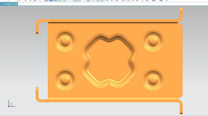
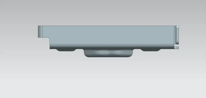
Upload a min of four screenshots of Model in the report.
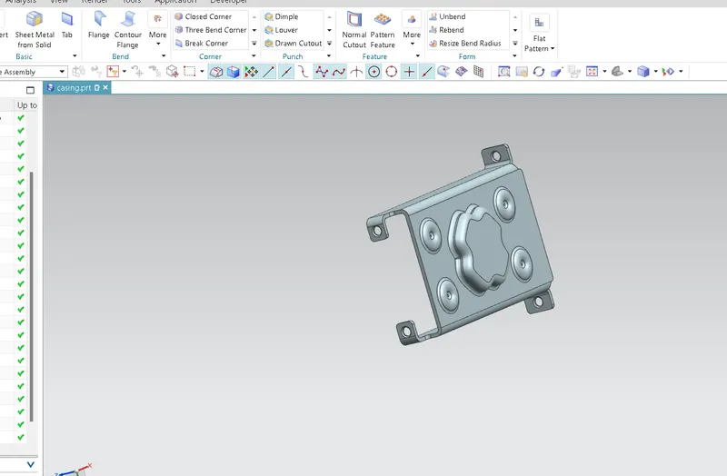
ISo view:
FV:
Tv:
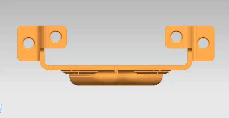
SV:
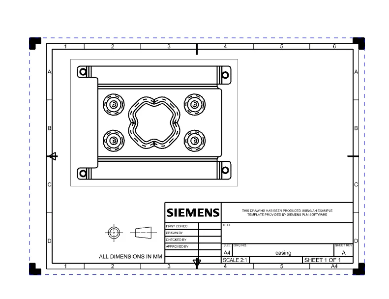
Attach Detailed Drawing Sheet Image:
Conclusion: Successfully design and learned advanced sheet metal operations.