Week 3:- BiW Fixture Design Methodologies Challenges
| What is Design Methodology? |
->
Design methodology is the steps followed during the concept design stages of fixture designs.
Design methodology are further classified into 4 main categories
-Purchase order
-Inputs from customer
-Percentage completion idea
-design input.
-Purchase Order: It is an order from a customer to start the work considering the specials in the PO .
-Inputs from Customer: It is necessary to understand the requirements of the customer to proceed with the design specs.
*Functional requirements
*Preferred Std components
*Car Products
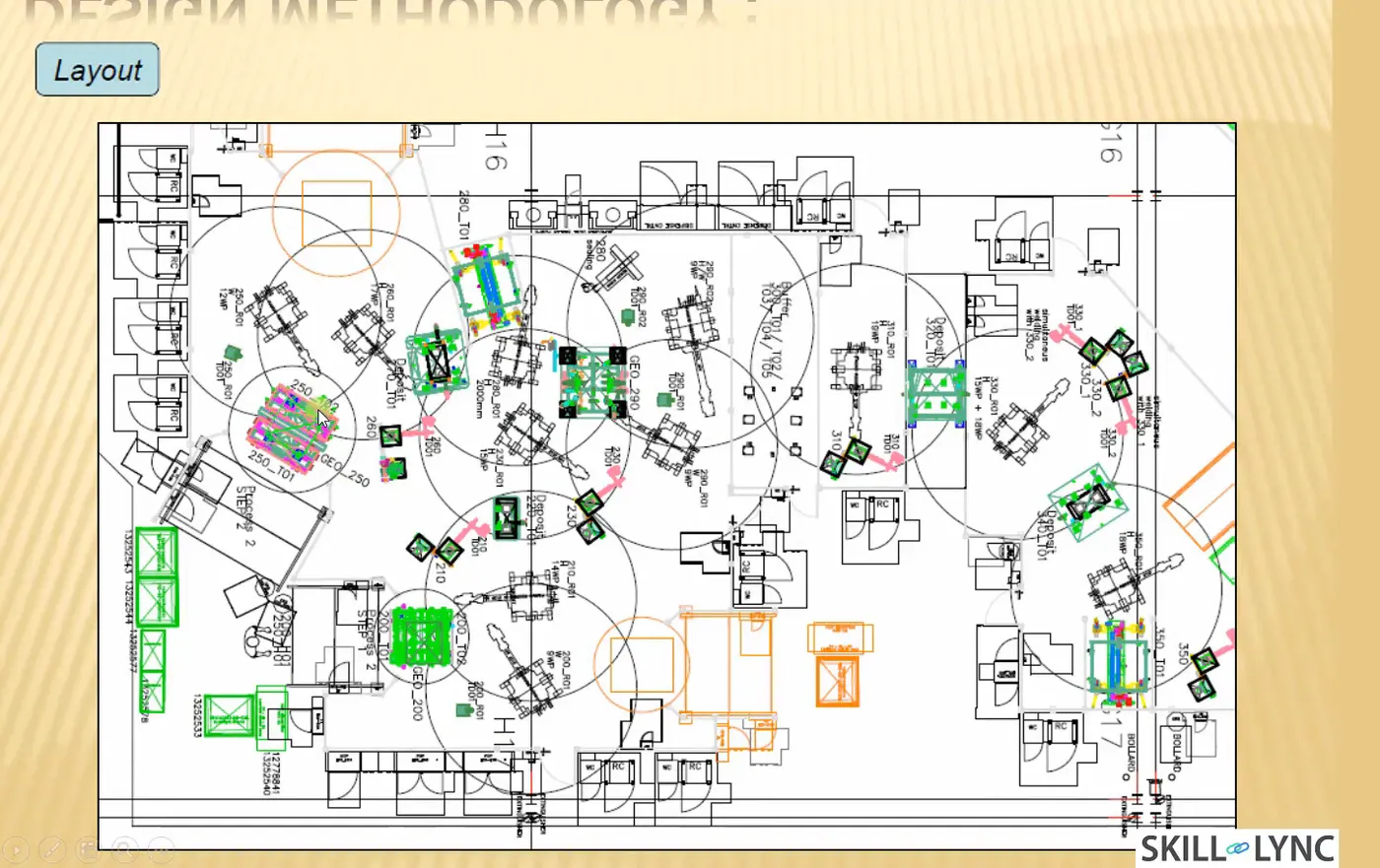
*Layout
*Ergo Data
*Weld Study
*Standard detailing templates.
-Percentage Completion Criteria:
It clarifies the completion of the project & gives overall idea of project Status.
0-25%: It includes inputs from customers & concept design.
25-40% : Concept application & Simulation checking
40-85% :Design Freezing & detailing
85-100% :Checkking & final dispatch.
-Design Output:
Outputs are 3D models & 2D drawing tools
Classified as
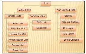
*Unitized Tools:I.e multiple units on a common base req. 2 types of drawing sheets.
-Key sheet->An index of units & their placements on tool base
-Layout Sheet->A detailed drawing of individual units to include all their components
*Nonunitized Tools: Tools that can stand alone & can be detailed completely on a layout sheet.
2.What are the inputs required from the customer to start designing a Fixture?
-inputs required from customers are functional requirements, preferred std makes, car products,layout, ergo data, weld study, standard detailing templates.
*Functional requirements: It requires different types of fixtures like,
Welding fixture, Hemming fixture, Checking fixture & storage racks
*Preferred std:
-Std likes ABB, NAAMS,DESTANCO,ZYTRAN,TUNKERS
-STD parts like Risers, L block, Retainers, Pins
-Components like clamps, cylinders, slides, switches, sensors.
-Weld guns,Tool changers, Tip dressers.
*Car Products: It consists of the below list
-GD&T
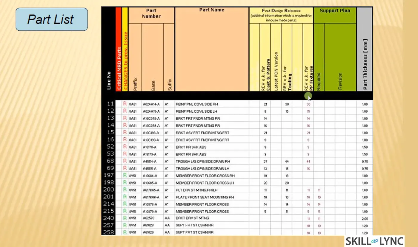
-Part list
-Cad files of CAR part
-Clamp Plan
-Product assembly process sheet
*Layout: It provides information of the following
+Flow of parts
+Station Pitch
+Robot stations
+Accesories like changer & tip dresser
+Sub assy links
+Platform Heights
+loading & unloading sequence heights.
-Ergo data:
It refers to study of human behavior & movements
It provides info on loading height, working safety zone of the operator, etc.
-Weld Study:
It includes weld gun details, & weld matrix & weld points i.e geo welding points & respots weld points
-Standard detailing templates:
It includes std templates to determine the position or correctness of the part.
3.What is the input we get from "Car Products"?
-Inputs from car products are GD&T, Part List, CAD files of part, Clamp Plan,& product assy process sheet.
GD&T: Provides information regarding the process for the part to be followed. It also provides information of locating pins,rest, Clamp, dump & slide information of each station.
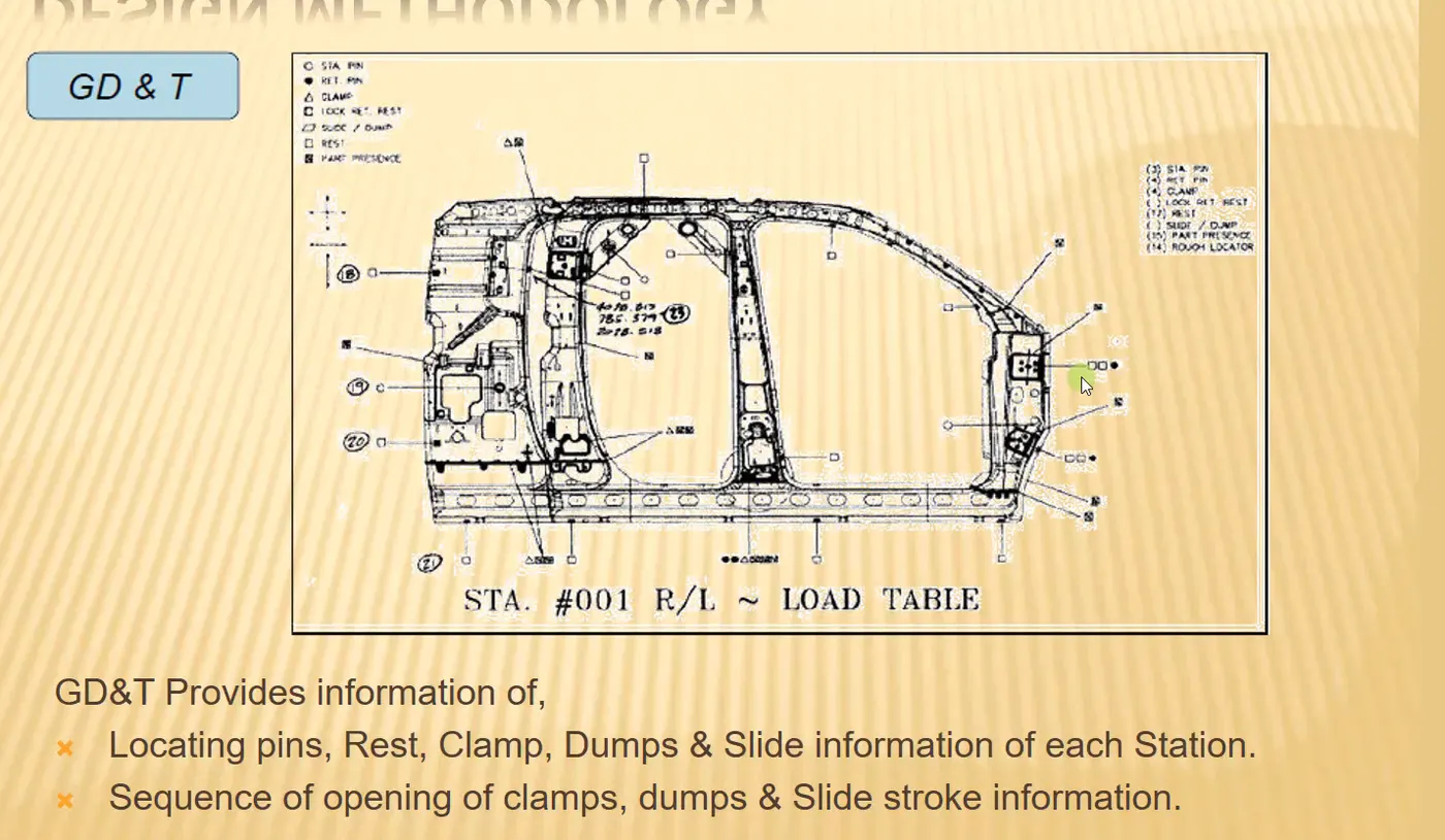
The sequence of opening of clamp, dump, & slide stroke information.
Part List: It consists of a list of materials, qty, moc, etc used in the particular assembly.
Clamp Plan:
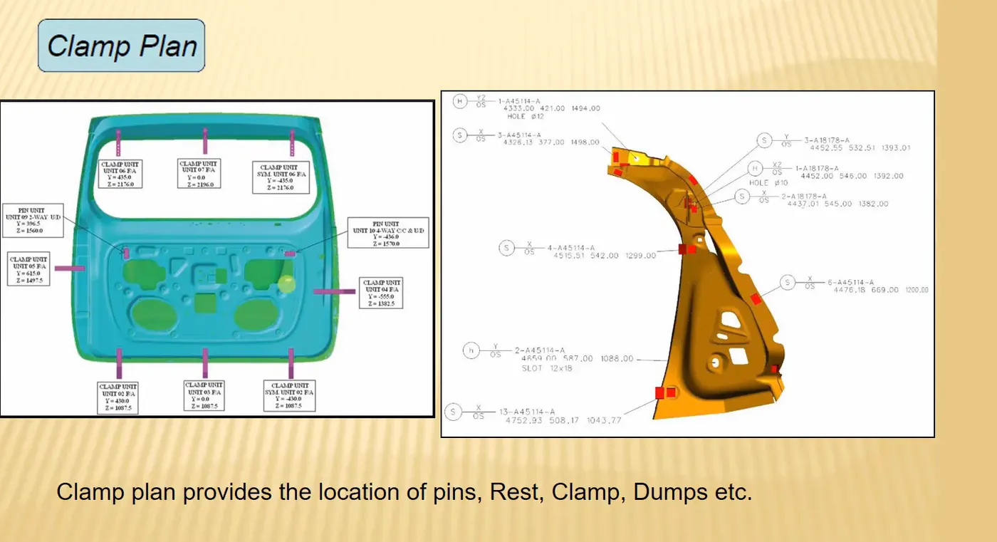
Provides the location of pins, roots, clamps, dumps, etc. The clamp plant should not be changed without seeking permission from the customer.
Product assembly sheet:
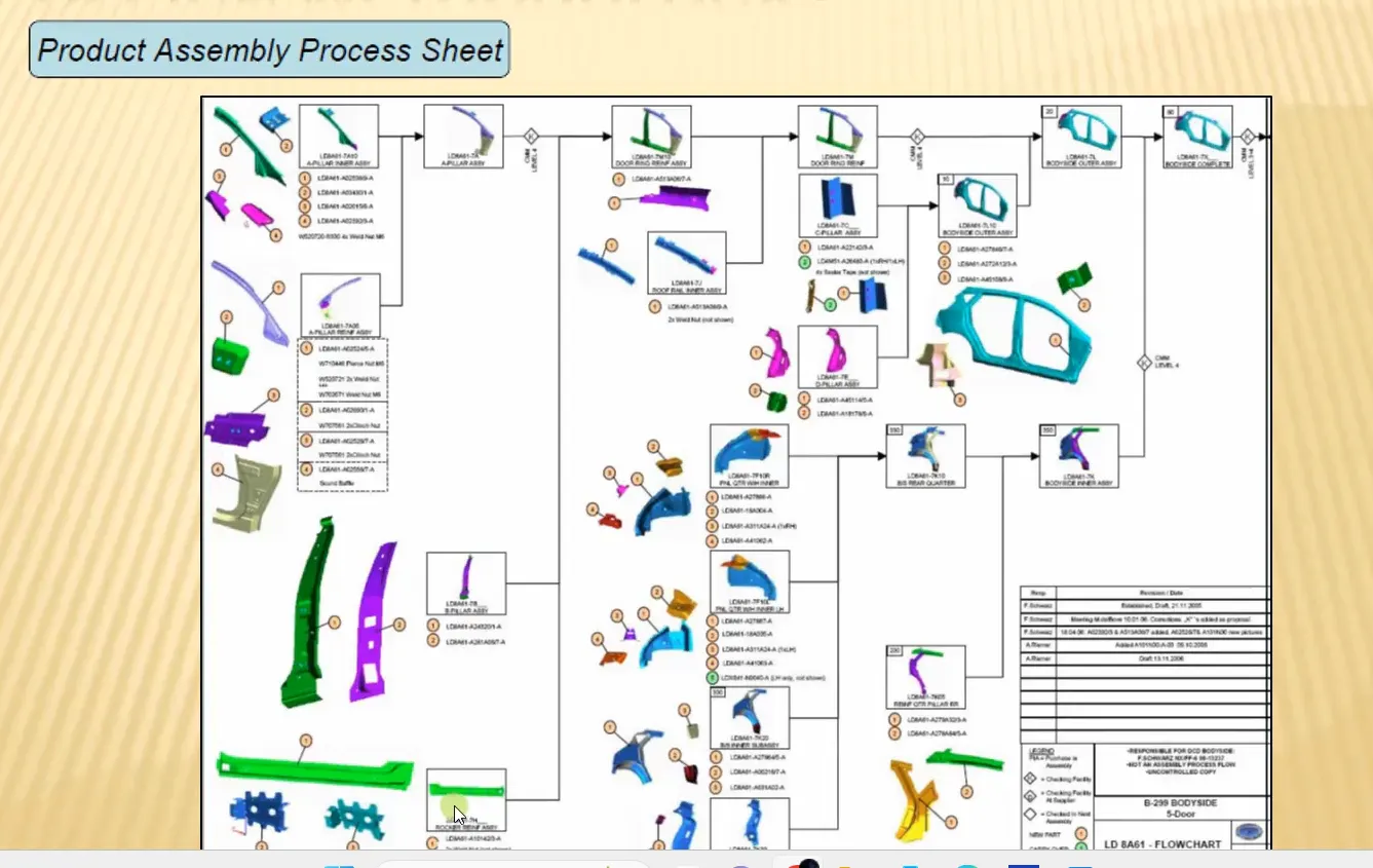
It is similar to the process flow diagram explaining all the child parts & assembly that are being assembled together to form final product.
-What is the Clamp plan?
Clamp plan is used to hold the workpiece is a fixed position in order to prevent the movement of the part.It provides the detail coordinates of pins,clamps etc of the fixture that are to be placed on parts.
Clamp plan will give us information about the area where the clamps will be fixed to ensure the proper geometry of the workpiece. We cannot change the location of clamp without approval from the client.
| What is the purpose of a Layout? |
-Layout represents the actual area being occupied & the process by the way it flows.
*It gives the plan of how the machine will be placed & how the parts move from 1 machine to another.
*It also implies the reachability of the operator or robot considering the minimum space required.
What is Ergo data?
Ergo data refers to study of human behavior & movements.It provides information of loadinng height,working safety zone of operator etc.
In any continuous operation, the operator attains different positions, exerts force, & works continuously in a cycle of time. This may cause strain on the operator.To avoid this principle of ergonomics is involved to improve man-machine behavior.
| What do you understand by Weld study? |
-
In the automobile industry, Welding is necessary to join the sheet metal components. Therefore the welding fixture is necessary so that the geometry of part do not change during welding.
In the above image, geo spots are shown in red & respot for the components in green.
Weld study includes weld gun details, weld matrix & weld points. The weld study gives the information about type of weld, temperature, type of current, approach of gun etc. Weld matrix & weld gun gives exact information of where the weld is to be done.
The geo weld spot is the primary operation where as where the welding is not possible is the geo welding fixture it is done in respot welding stations.
| What are the criteria for percentage completion in the designing stage? Explain it in detail |
To analyze the completion of the project activity it has been categorized into 4 percentage stages .
0-25%: In this input from the customer is taken & by studying this input concept design is made of the fixture.
25-40%: In this concept approval & simulation are checked.1st after getting approval from the customer we will then proceed for simulation on the fixture.
40-85%:Design freezing & detailing.Once the design is approved from the customer we will then proceed for detailed 2D drawings of the parts. Once parts are made they are assembled together to form the whole model.
85-100%:Checking & final dispatch. Once the product is ready then we will check the product if it intends to give the desired output. Once the checking is done we will then disassemble the assembly & proceed with packing.
| Brief about "Output" in design? |
-The output should compile of following points
*Approved std components to be used wherever possible.
*Design to be simple an economical
*Design must comply of all safety & ergonomic requirement
*Design must provide full control and damage-free handling of the product.
*Adequate error-proofing must be incorporated into each design by providing proximity switches, rough locators, etc.
*The weight of the moving part is to be kept minimum while providing maximum strength.
*Frames & structure are to be simple & sturdy.
*Appropriate clearance & accessibility for routine maintenance & service.
*Design is responsible for validating all clamps& all weld gun.
*Motion control must be considered on moving equipment.
| What do you understand by structuring a design tree? How does it reduce errors during the design process? |
-It implies all the Assy. & parts are named in a specific std. The different customer has a different set of std to structure the design tree.
*It is an important process which helps to identify specific parts or assy. & where it belongs.
*This helps us to avoid errors during design studs, manufacturing, assembly, inspection, etc.
*If the part or assembly is not named properly or the design tree is not structured properly it will create confusion in understanding the design& may create major possibilities of making an error.
*Namin the assembly, a unit, a part, or a fixture helps in recognizing in which area or zone the part belongs.
*It can help us understand the qty of items same or different that are being used in an assembly.
| What are Units? Mention 5 types of units. |
-A unit is a part designed for a specific purpose & is also a part of a complex assembly.The biw fixtures is an assembly of to many units which are used to perform different functions . They are classified into unitized & nonunitized tools.
5 different types of unitized units are
-Rest unit: Used to rest, support car panel using NC blocks/mylars/rest, etc.
-Fix pin unit: arrest the movement of car panel or product component.
-Retractable pin unit: It is a retractable pin unit mounted on the pneumatic cylinder which is designed to locate the car panel using pins having a retractable mechanism.
-Rough Locator unit: It is designed to guide the operator to locate the car panel onto the pins accordingly.
-Base unit:It is designed to mount all other units of the tool on it. It forms a rigid structure.
| Describe Fixed Pin units & their purpose? |
-Diagram:
Fixed pin is designed to locate the car panel using pins. It is nonmovable unit used to orient the part & constraints all the movement of the part.
Different parts of fixed pin unit in general are:
+Pin
+Pin retainer
+Shims
+spacers
+Block
+Blade/adapter block
+riser
The purpose of the fix pin is: To locate the car panel & arrest the dof of the car panel.
| What are the different parts of a fixed unit? |
-Pins:Pin is a part that locates the car panel.A pin can either be made part or std. part.
-Pin Retainer: A pin retainer is a part that holds the pin in position. The retainer Pin can be made part or std part.A Pin retainer should have a hole with a fit, on to which the pin is fixed.
-Shims/Spacers:Shims and spacers are std part in general,which are used for adjusting of locators, cnc blocks & pin locators w.r.t the part.
-Block/L Block: These parts are mainly used to accommodate the shimming direction.
-Blade: It is part like plate that connects the part of the unit to riser. It can either be a make part or std part.
-Riser: It is a part on which all parts of the unit are mounted & is mounted on the base plate of a tool.
| What is the purpose of making a Rest unit & describe its parts? |
-Rest parts are designed to support /rest car panels using NC blocks,mylars. Because of its simple design it is combined with to reduce the number of parts.
It consists of the following parts
+NC block/Mylars:It is a part that holds the material from top & bottom.Mylars are of 2 types, clamping & resting. Mylars have jaw like shape which improves the holding of the part.
+Spacer: Shims & spacer are of varying thickness. They are used so as to adjust the space between the part.The thicknes of this parts vary from 0.1,0.2,0.5 etc.
Blade: It is part like plate that connects the part of the unit to riser. It can either be a make part or std part.
Riser: It is a part on which all parts of the unit are mounted & is mounted on the base plate of a tool.
| What are the basic fundamentals to design a Sensor unit? |
This unit is designed to sense car panels by using electrical sensors.The signals from the sensors will be fed to the PLC& so the next process will be executed by this signal.
Fundamentals:
*Every loose panel which is being welded in a tool should be sensed.
*Each sensor should be sensed by 1 or more sensors dependent on the size of the panel. Preferred to be diagonal in opp. ends of panel.
*Every sensor should be mounted in a 3D adjustable ways.
There are 3 main type of sensors,
-Proximity
-Laser
-Photoelectric sensors
| What is a Rough locator unit & what are the basic fundamentals to consider while designing it? |
It is designed to guide the operator to locate the car panel onto the pins accordingly. A rough locator can be a std part or a make part.
Fundamentals;
*Rough locators are to be placed at the edges of the car panel, which it has to guide.
*Rough locators have to be placed at the same angle of the car part edge with a minimum distance of 2-5mm from the edge of the car part.
*It should guide the panel in Pin arresting direction.
*It should guide the panel before 10-15mm to the start of the pin engagement.
*Should be designed with an entry angle for car part entry.
*It is designed with 2 slots to mount for easy adjustments.
*The slots should always be in the direction of the car part guiding.
| What is a Base unit and describe it's parts? |
-Base unit is designed to mount all other units of the tool,also other parts necessary for tooling like pneumatic valve box, etc. trunking cable path will also be mounted on base unit.
Parts of Base unit:
-Trunking channel
-Base plate
-Valve Box
-Measuring Hole cover
-eye bolt
-Pedestrian
-Weld bars
-Floor plate
| What is a Dump Unit and what are its functions? |
Dump system is used when we have to space constrain.When we have geometrical connstrains & we cannot mount clamps, rest unit , etc. we use dump unit.
It consists of a dump cylinder to perform the operation of clamping & unclamping.
Funnction:
-if there is no space available or less space we use dump unit.
-It is a dump cylinder that performs the operation of opening & closing of clamps.
-Copmplex by design only used when if it is needed.
| What is a Slide unit? Mention where Slide units are commonly used. |
-Sliding unit are used to position the car panel, units for further operation. Sliding units are used in places where we have space constraints & different units cannot be used.
It consists of following parts:
-Guide Rail
-slide cylinder
-Guide block
-Sensor unit
-Stopper block
-Position Locking unit.