Project 1
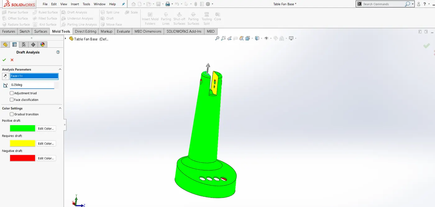
Step 1 : Check the drafting angle. Drafting angle varies from 0.25 deg to 7 degres. Select the tooling axis perpendicular to selected surface from where maximum no. of faces get cleared.
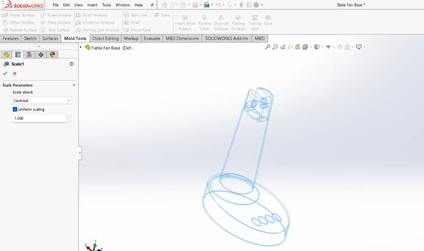
Step 2: Scaling. Since material considered is ABS its shrinkage value is 0.6 % i.e it requires more 0.6% material to satisfy the mould.
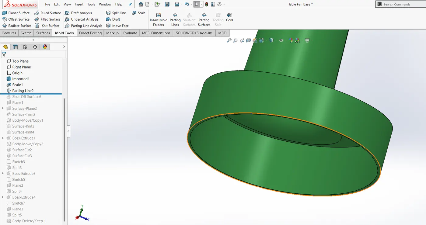
Step 3:Parting Line. The Line that seperates core & cavity block is called as parting line.
Step 4: Shut off surfaces. Inorder to seperate Core & Cavity blocks open areas in the parts need to be shut off. The places where undercuts are pesent the area may be kept open.
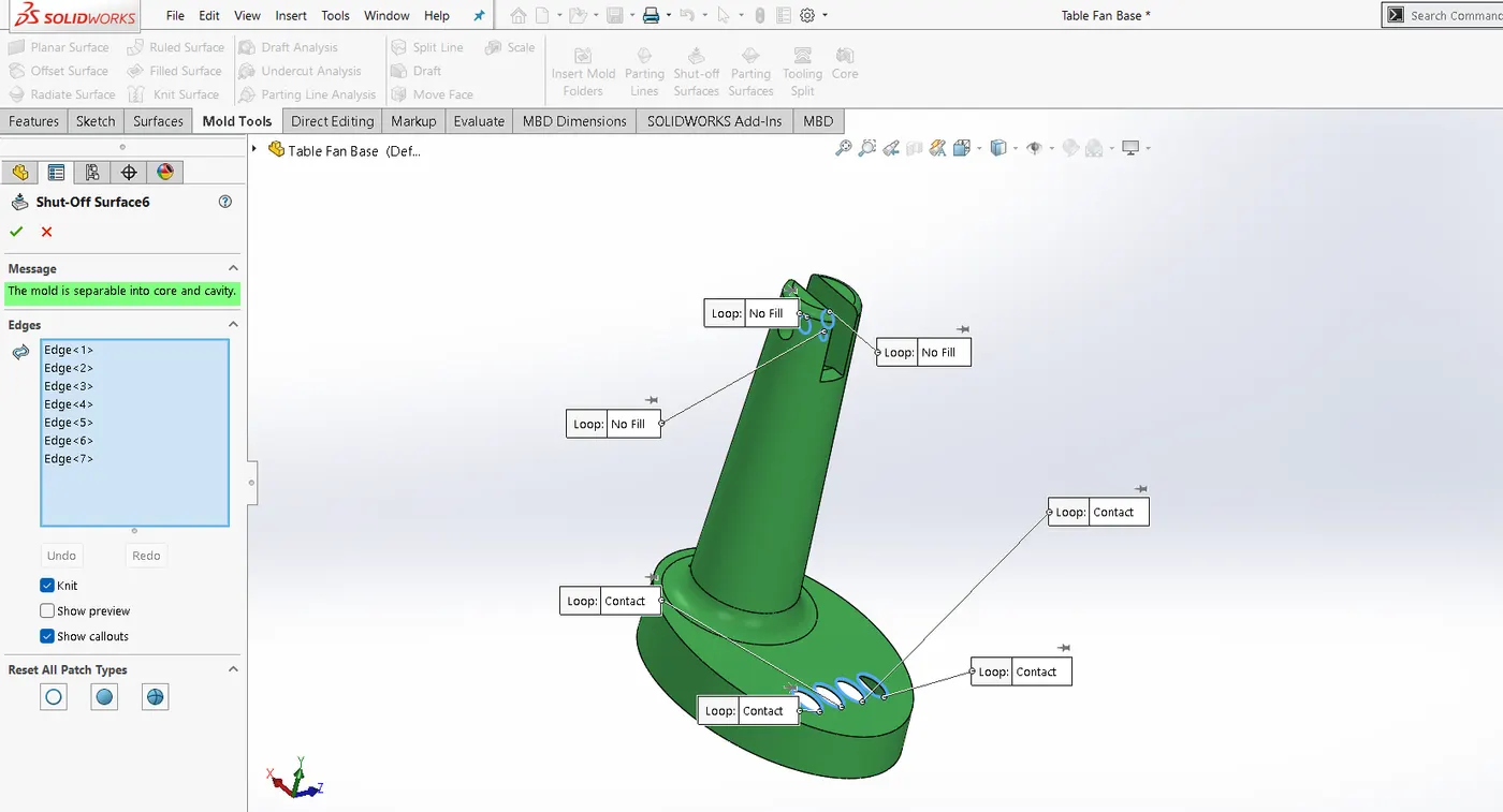
Step 5:Shut off faces helps to create core & cavity surfaces.
Step 6: creation of planer surface. The surface where Core or cavity seperates along a single plane is called planner surafe . Here it is 2D in nature.
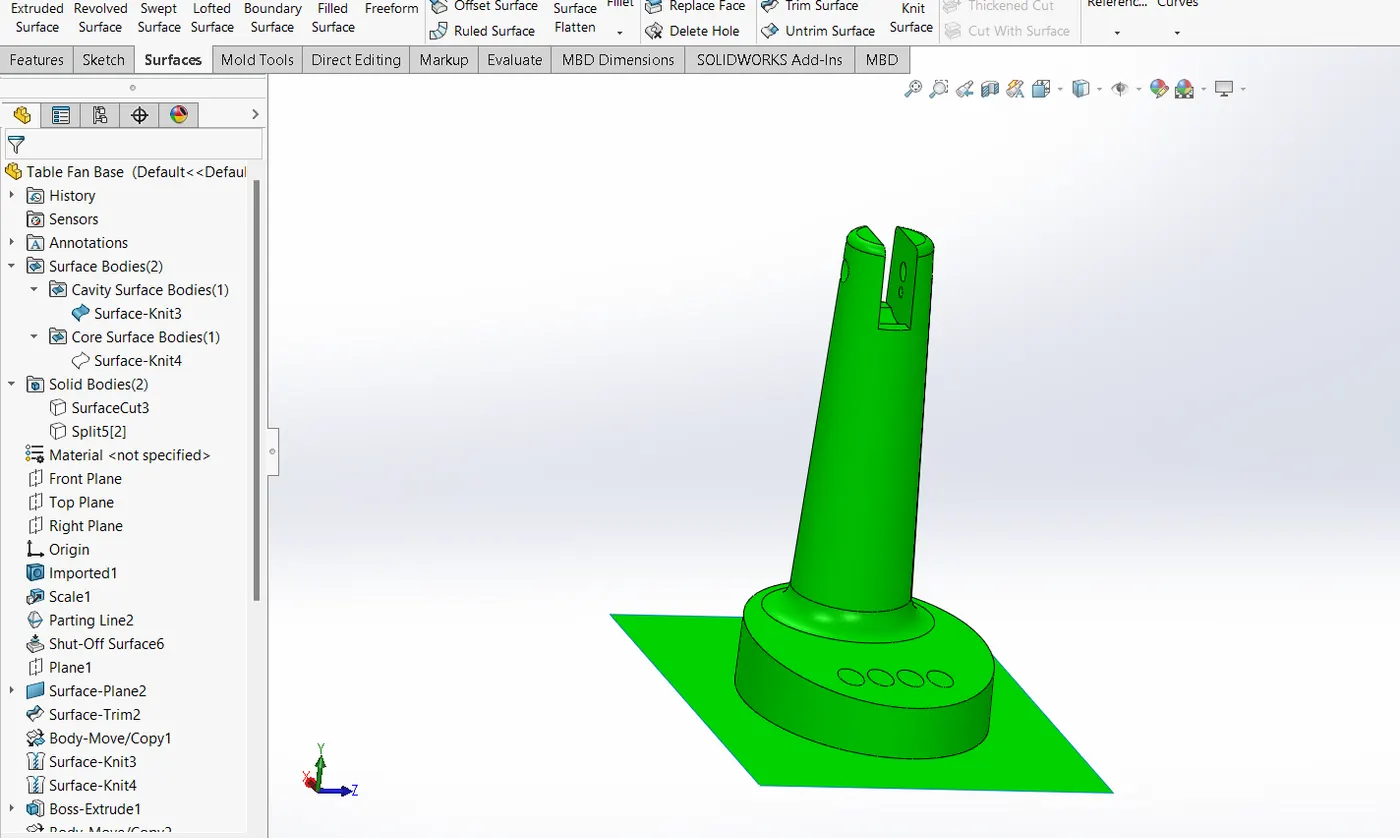
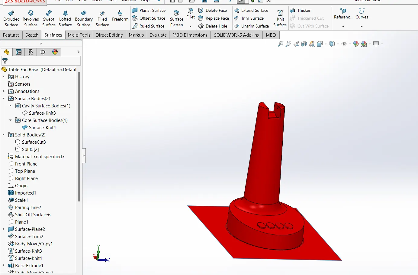
Step 7: Creation of Core & Cavity blocks. The core & cavity surfaces are merged together to form a 2 different curfaces.These surfaces are the cut with surfaces to form the respective core & cavity blocks.
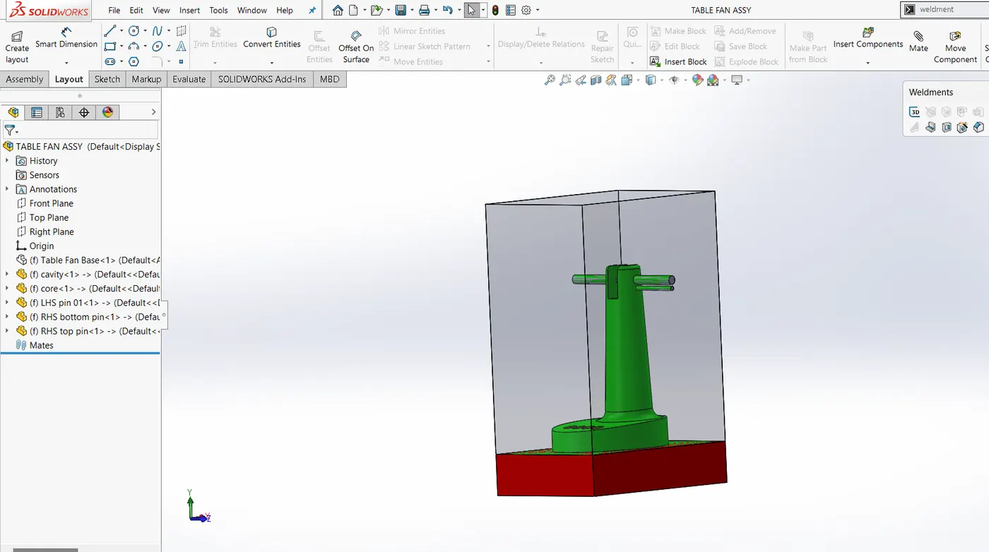
Step 8: Sliders /Pins for undercuts.
The profile of undercut is directed on plane,& then by using split command respective pins are created to achieve desirable cavity block..
Google drive link:https://drive.google.com/drive/folders/1JfhuIhyzBtDNOpuiH3fJ7BYm1Qjzv1ZM?usp=sharing