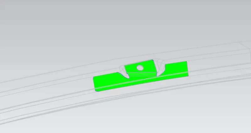
Design of backdoor
Design of back door:
Requirements to design the back door:
- The back door should be designed in such a way that it follows the tagectory .
- It should contain hinge ,gasstay reinforcements
- It should have the rear visibility criteria
- It should contain wipermotor mounting region etc
Material used in the design of back door:
Generally the material used is steel. By using steel parts, they can easily be maufactured using stamping process. The product of uniform thickness is used while manufacturing the party. Currently most of the companies have also started using Aluminium, since it is lighter in weight.The parts produced by aluminium is by using casting process.since the parts are cast there is no meed of necessary reinforcements to be provided.The parts produced by aluminium can also have different thickness according to use.
Load cases (back door):The design of backdoor should also satisfy the load cases,
- Bend
- Torsion
- abuse case
- dent test
- assembly load test
- endurance test
Techniques/process used while manufacturing the part:
Stamping process: It involves placing flat sheet metal (0.4 to 6mm thk) , in either coil or blank form, into a stamping press. In the press, a tool and die surface form the metal into the desired shape. Punching, blanking, bending, coining, embossing, and flanging are all stamping techniques used to shape the metal.
Hemming Process: In hemming process the edges of the sheet are bend inwards upto 180 degrees to join the sheet.Hemming is done to improve the appearance , act as reinforcement,and to connect the parts together.
Brazing Process: It is used to join metal surafces using molten metal. The filler metal has lower melting temperature then that of molten metal. Eg , Joining of Outer upper and lower pannel,Section near rear visibility is joined using brazing process.
Design of back door:
Given the parent surface , the part bodies are extracted to form the require sections to form the desire part bodies.
1.Outer upper pannel
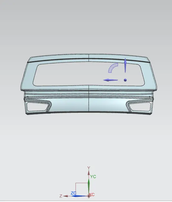
fig1.1-outerupperpannel
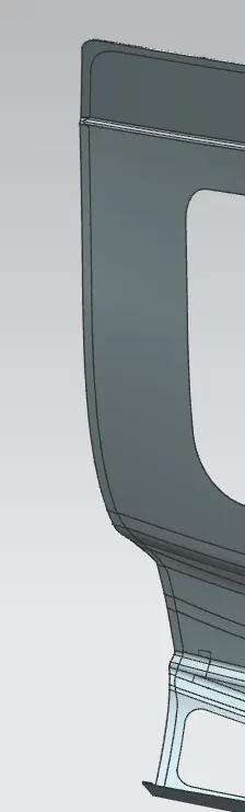
fig 1.2: Hemming section
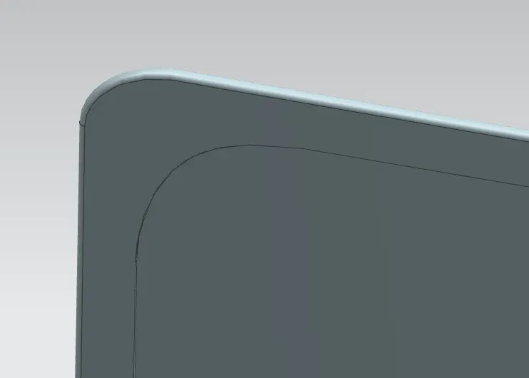
fig 1.3 Relief at top
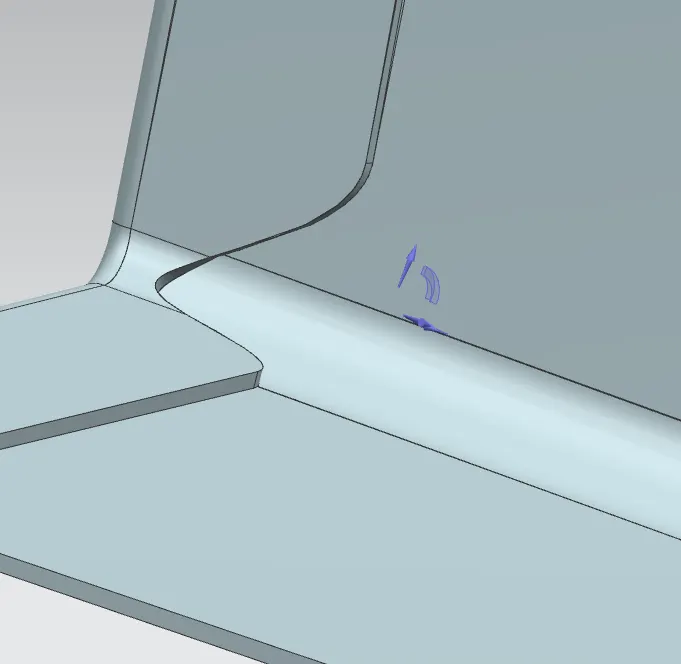
fig 1.31 Relief at bottom.
2. Lower Pannel
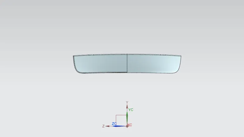
Fig 2.1 Lower pannel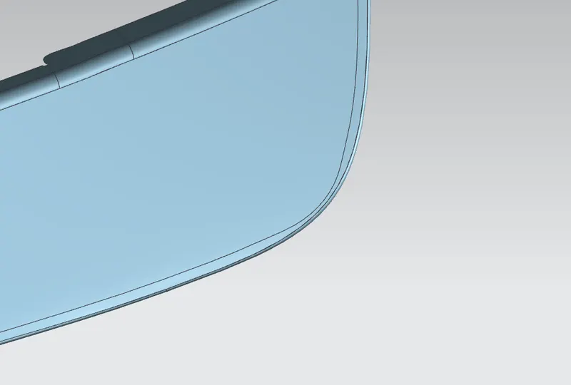
2.2:relief at top of lower pannel
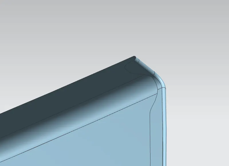
2.3:relief at bottom of lower pannel
3. Inner pannel
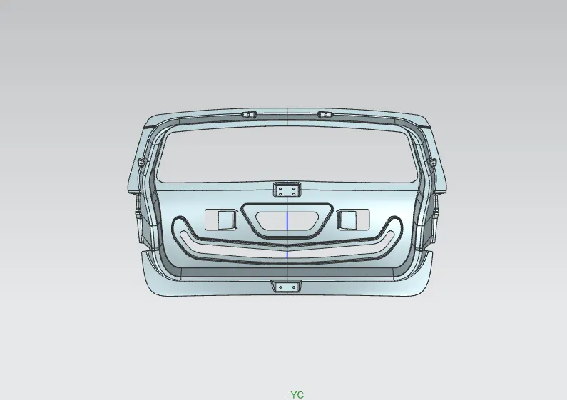
Fig 3.1 Inner pannel.
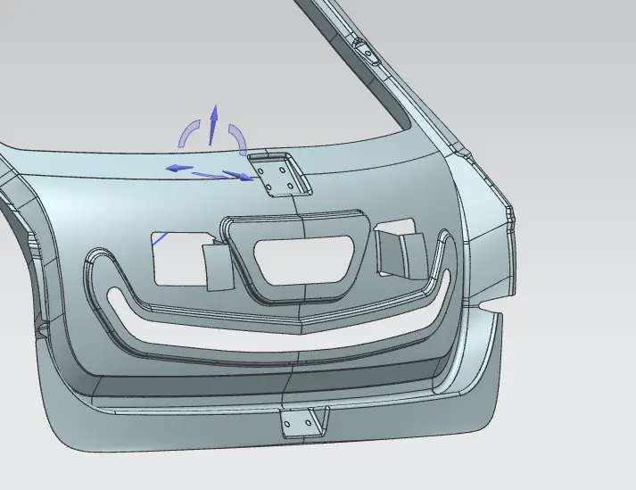
Fig 3.2 Lancing for pannel.
4. Hinge reinforcements.
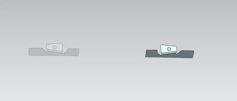
Fig 4.1 LH RH reinforcements
5. Gasstay reinforcements.
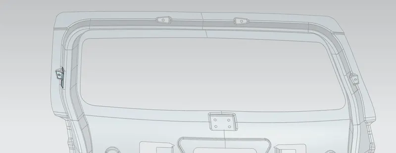
Fig 5.1 Gasstay reinforcements.
6.Motor mounting reinforcements.
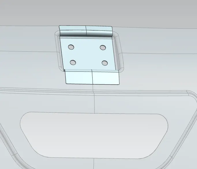
Fig 6.1 Motor mounting reinforcements
7. Latch and stricker reinforcements
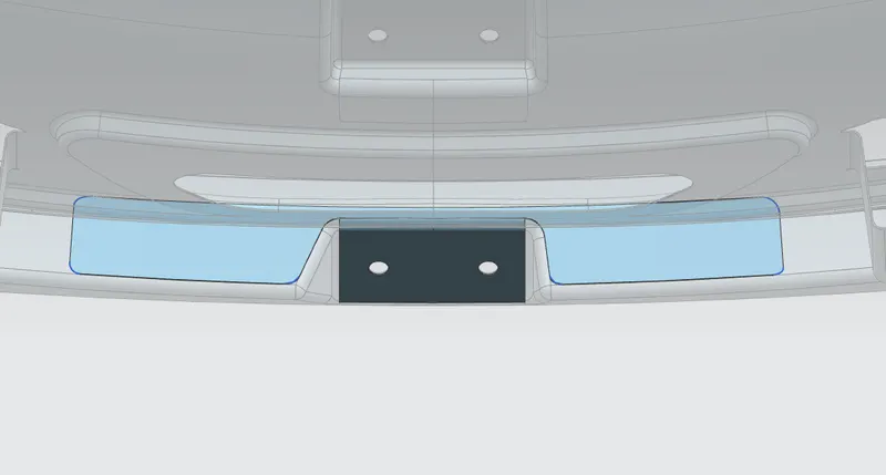
Fig 7.1 : Stricker reinforcement
The outer and lower pannel of the backdoor forms the apperance look and therefore should not have any surface irregularities. The outer upper pannel and lower pannel are connected to each other through the brazing process.
Inner pannel forms the main structure of an automobile . The inner pannel should be designed in such a way that it should trasmit the force outwards during collisions for the safety concern. The inner pannel consists of embosses and lancing structure. The embosses strengths up the back door and reduces the force by transmitting it outwards.Therefore the embosses created should be in V section or else in the Y section which helps in transmitting the force. The inner pannel also consist of lancing process which connects the outer and innel panel to each other.
The innerpannel consist of different embosses namely gasstay emboss, hinge emboss,latch stricker emboos , motor mounting emboss. Also the inner pannel should be thicker so that maximum luggae space can be obtained.
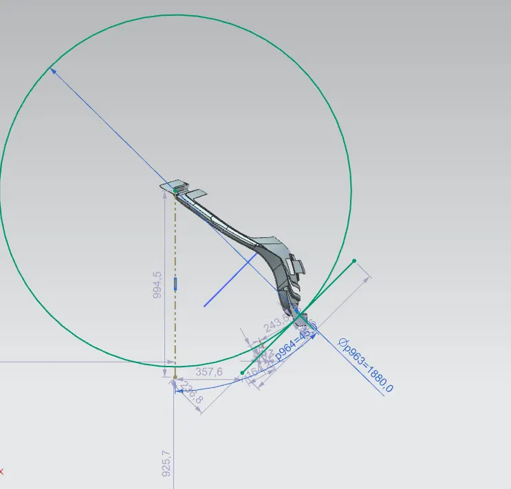
The stricker emboss is created by using the trajectory .
- The trajectory is formed by connecting the line (CTC of hinge holes) using line command.
- From the centre of line i.e midpoint a circle is drawn that innersects nera to the ceiling flange.
- tangent to circle a line is drawn. Now another line is drawn perpendicular to the intersection of tangent trajectory .
- Now emboss is created from the line perpendicular to the tangent trajectory using law extension command.
therefore we therefore achieve plane emboss that is perpendcular and follows the tangency criteria.
8. Draft analysis
8.1 Outer Upper panel
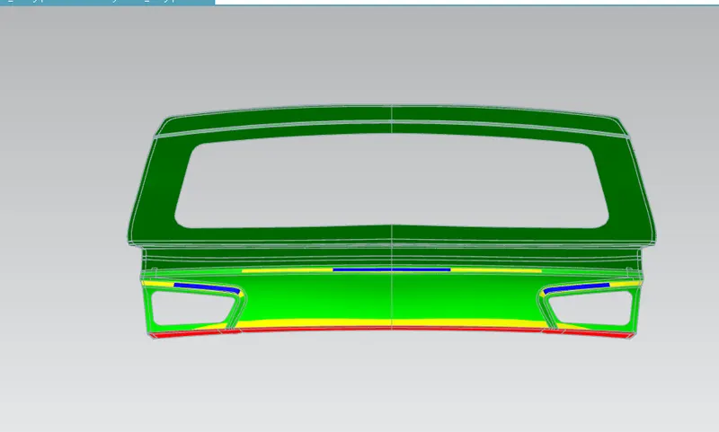
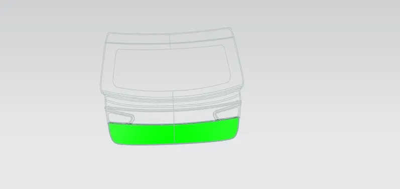
8.2 Outer lower pannel
8.3 Inner Pannel
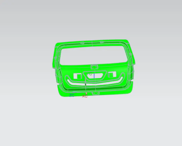
8.4 Reinforcement