Week -2
- Make a Simulink model of Doorbell using solenoid block with the following details:
In the above arrangement, when the switch is closed the electromagnet receives electrical power from the battery and pulls the metal arm to hit the bell producing sound.
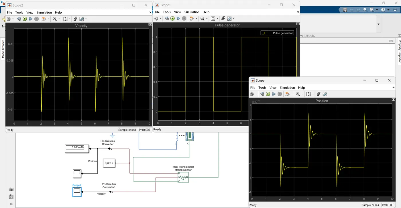
Create a situation where the switch is closed for 2 seconds and then released. Observe the physical movement of the plunger.
--> In the above description it is clear that the signal to be square wave. Considering the time period to be 4 seconds.
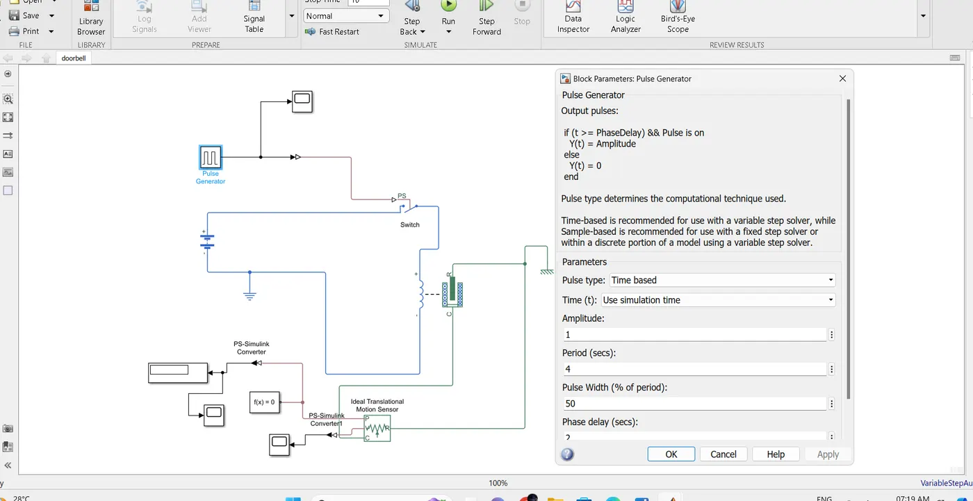
Blocks required: Pulse generator block, switch, solonoid valve,Battery,Ps simulink converter, simulink to PS converter, Motion sensor,solver block, display,scope.
Pulse generator block: The pulse is generated every 2 seconds representing the bell is rang.
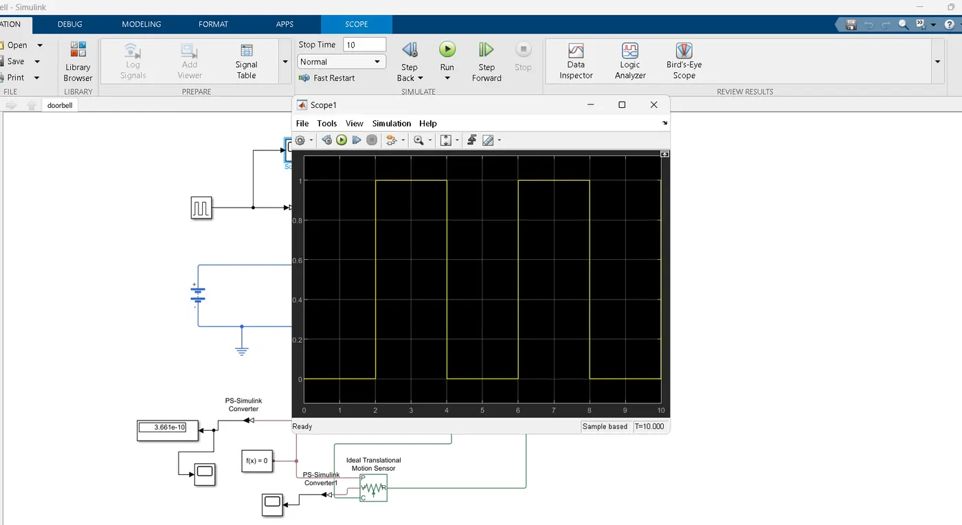
Switch : Switch is real time analysis tool which takes input signal from signal generator & depending upon the condition it is either open or closed.
Solonoid valve: After receiving the signal from signal generator,when the switch is closed the circuit is closed thus the signal is passed to solonid valve, from where the signal is translated to ideal translation motion sensor. The ideal translation motion sensor activates only after receiving the current from solonid valve i.e after every 2 seconds.
Solver Configuration: Defines the solver seetings for the given configuration.
Scope:Display the signal based on input provided.
Reference: Electrical & mechanical reference is provided for grounding & support structure.
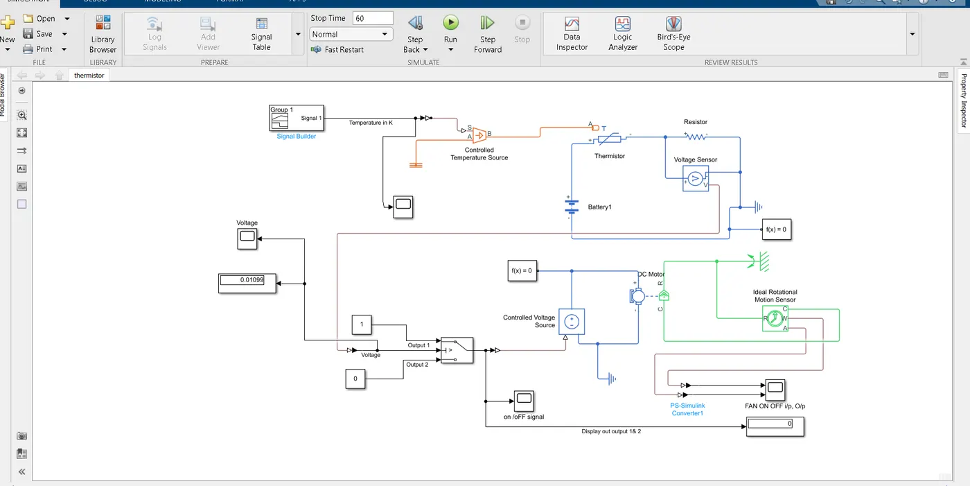
Q2.Use a thermistor to sense the temperature of a heater & turn on or turn off the fan as per the below conditions:
Temperature source: 20 °C from 0 to 10 seconds, 27 °C from 10 to 30 seconds, 23 °C from 30 to 50 seconds
Fan conditions: ON if the temperature above 25 °C, OFF otherwise
-->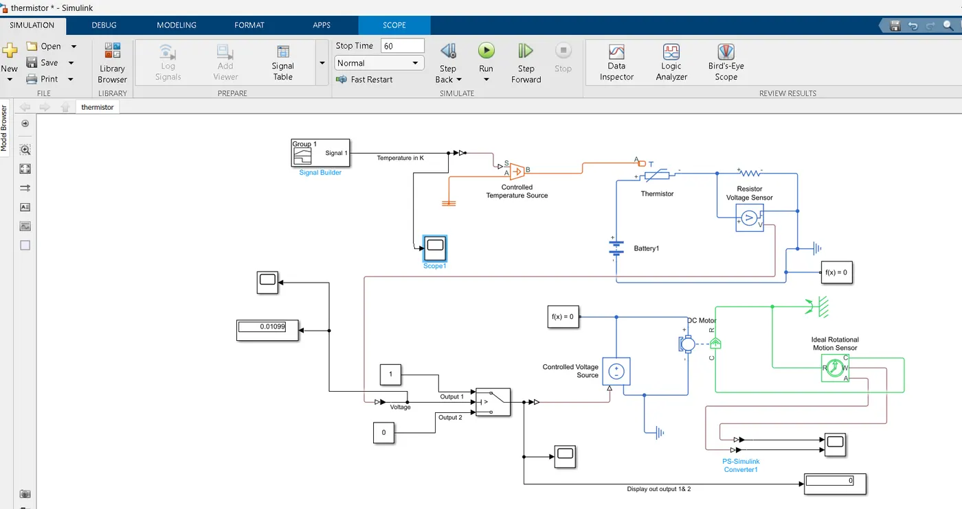
Block diagram of thermistor challenge.
Aim: To on the Fan after the temperature is reached 25 deg C or 297 K.
Explanation:
-->Using signal builder block we are creating varying signal according to the given temperature inputs.
-->The temperature controlled source maintains the temperature difference regarless of heat flow.
--> The Negative temperature thermister decreases resistance with increase in temperature.
-->Resistance: Offer resistatnce to the flow of current.
--> Voltage block is used to measure the voltage. The voltage value at which temperature value reaches 25 deg C is calcaulate using interpolation.
Here at 20 deg C (293K) , 25 deg C (298K)& 27 (300K) deg C, the corresponding values are 9.739mV, 11.77mV,12.59mV.
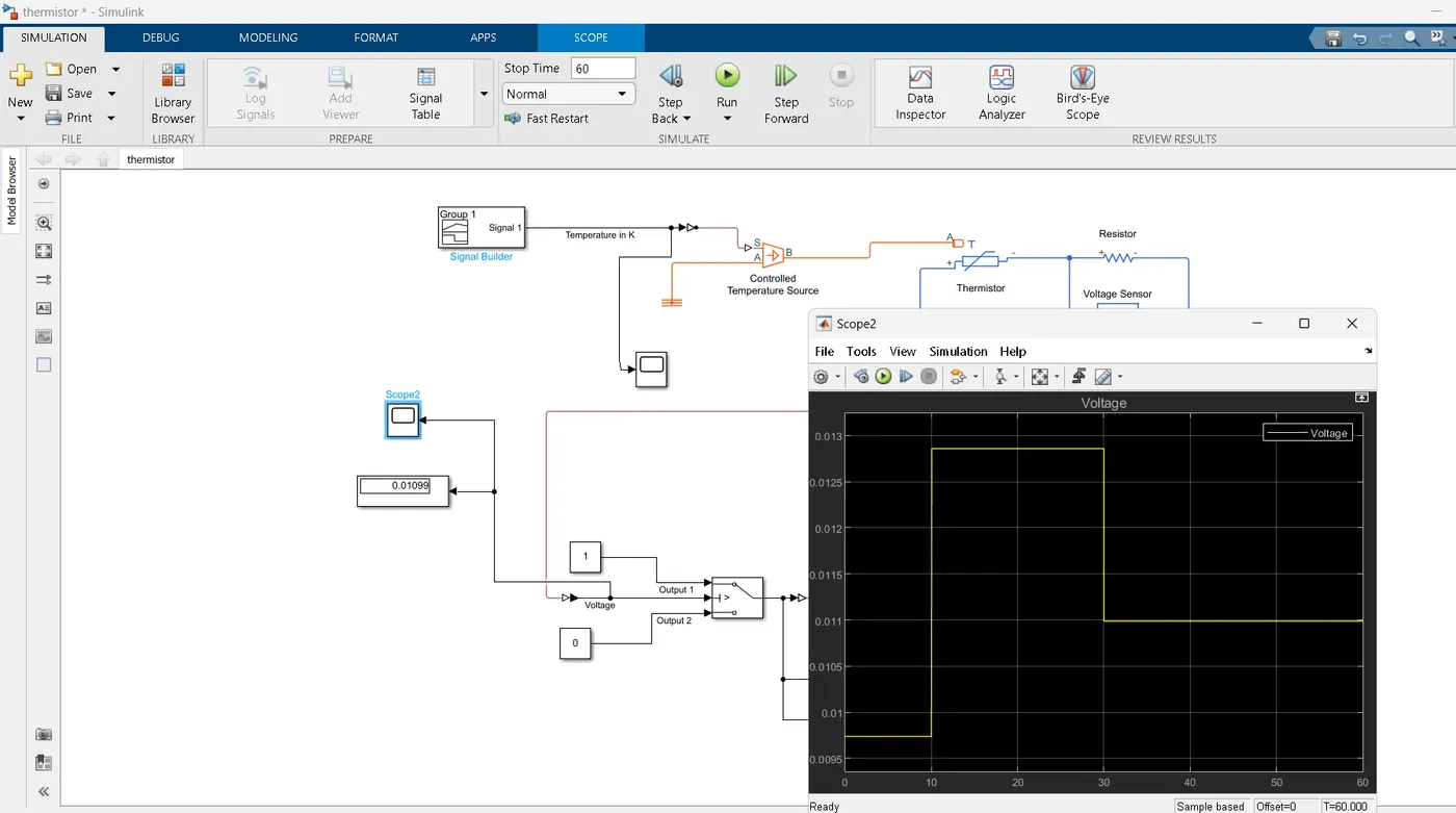
--> This voltage value at 25 deg C or 298K is used as thereshold value i.e as soon as the value of voltage reaches this value the switch will trigger & Fan will get on.
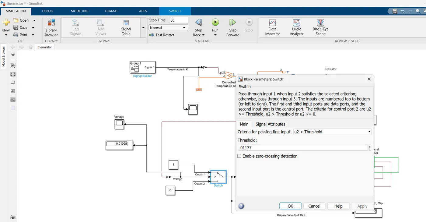
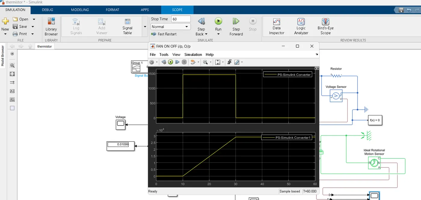
Thus we have succesfuly designed the system that turns the fan on for the cooling of the system to maintain the depereature below 25 deg C or 298K.