Week 7:- Base Unit Design Challenges 1
What is the Base Unit? What are the typical parts of the Base Unit?
-> Base unit is a unit that is designed to mount all the other units(Clamps, Pin, Rest, L blocks, etc) of the tool, as well as other parts necessary for a tool like a pneumatic valve box. The trunking cable path will also be mounted into a base unit.
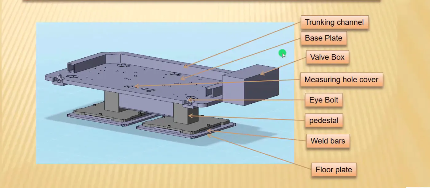
Some parts of base unit are as follows:
-Trunking channel
It is a type of duct that carries all the pneumatic & electrical connections.
-Base plate
It is a machine plate of thickness varying from 25mm to 40mm made of steel aluminum, on to which holes are drilled to mount the individual units like clamp unit, pin unit etc of a tool.
-Valve Box
It is a standard part that contains all the valves for the pneumatic operation of the unit. It includes solenoid valves. The pneumatic fixtures work on air pressure provided to it. The pressure release in & out is controlled by the valve box.
-Measuring hole cover
Holes are drilled over the base plate so that reference can be taken from every hole which are having the exact coordinates. This holes are covered by the plate to protect from other dust & other particles.
-Eyebolt
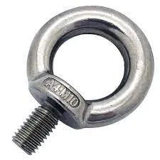
Eye bolts are used for transporting the tool, using lifting hooks. A forklift hole will also be provided in some cases.
-Pedestal
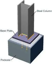
It is a part that connects the base plate to the floor plate. A pedestal is a std part in general & in some cases it can be welded frame integrated with a base plate.
*A std pedestal can be of different height & size
*Depending upon the size of the base plate the no. of pedestal varies for load distribution.
*A pedestal is of different types with different indications.
-Floor Plate
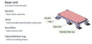
Floor plate is grouted to the floor with fixed bolt on the ground. Floor plate is also called as foundation plates.
*There will be a clearance of 10mm maintained between the pedestal base plate& floor plate.
*This clearance will be used by leveling screws, for leveling of the entire tool
*Weld bars are be used to weld the positions permanently after leveling is done.
-Weld Bar
A weld bar is a plate along the sides of the base plate of the pedestal.
What are the points need to account while designing a Base unit?
*Fundamentals:
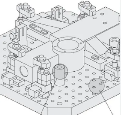
-A base plate size should cover all the units with its outer periphery including the opening
-A base plate is designed with a Body coordinate system
-A base plate should be drilled with datum holes/Measuring holes lined with a pitch of 1000mm in general.
-No. Of datum, holes depend on the size of the base plate
-Datum holes to be drilled at nominal values in terms of multiples of 50s & 100s
-Datum holes to be drilled with dia 100mm away from each other units
-Datum holes should be covered with cover plates.
What is a Dump unit?
-A dump unit is a positioning unit that is used to position car body parts in BIW welding fixtures when there are geometrical constraints that prevent the use of std positioning.
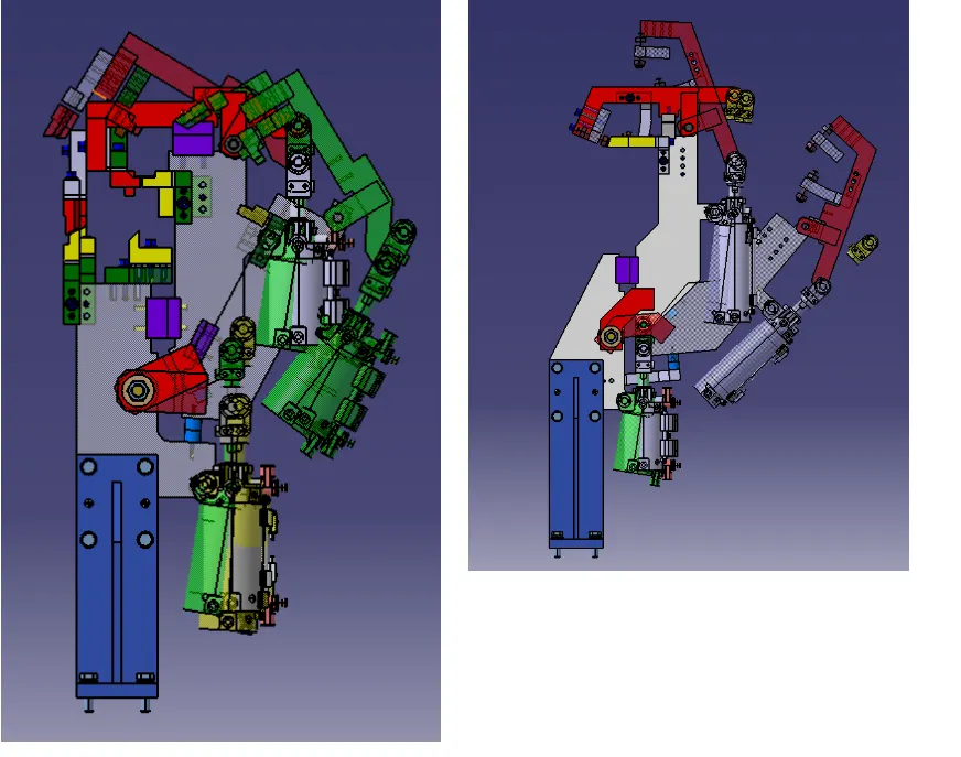
FUnctions of dump unit:
-Proper resting of panel being welded
-NO rotation occurs
-Correct shimming to be provided.
What are the points you need to consider while designing a Dump unit?
-Dump unit is considered where there are space constraints.
-It contains a dump cylinder which is a heavier part in all units, but can do all the functions effectively.
-The parts to be designed considering the open conditions of the units.
-The riser & blade should have enough strength to sustain the load of the cylinder
What is a Slide unit?
-Slide units are position units that are used to position weld guns, units, and robots into further operations. Slide units can be classified into 3 major types based on the prime mover used;
+Manual
+Hydraulic
+Pneumatic
What are the points you need to consider while designing a Slide unit?
- Sliding units are used when there are space constrain
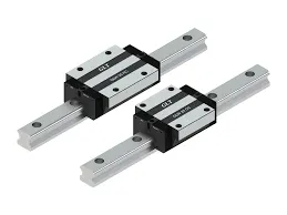
-LM guide ways are preferred over hardened guide ways due to less coeff. of friction.
-Slide unit essentially consists of LM guides, Linear cylinders, Front & rear stoppers, Shock absorbers, Proximity/reed switches for end positions, and bellows for protection.
-Reverse stroke of 10mm to be considered inn both forward & retraction direction.
-Cylinder & LM guides to be validated for load & stroke
-LM guide rail length should be std.& more then actual stroke.
-Mechanical hard stop to be considered.
-Shock absorbers to be used at both ends.
-The end limits to be sensed externally by proximity switches.
-Shock absorbers to be mounted perpendicular to mid stroke vary to +-5 deg