Project - Position control of mass spring damper system
Aim: To build a spring mass damper system with PID using Matlab Simulink.
Procedure:
-1st to generate a pulse signal as shown in the question.
-Since the given question is spring mass damper system, equate the eqn as follows.
mx_ddot + k* x + c * x_dot= F(t)............ eqn 1
where
x_ddot- acceleration
x-displacement
x_dot-velocity
F(t)- forcing function.
x2 = x1_dot...........eqn 2
mx_ddot = F(t)- k* x - c * x_dot
x_ddot = 1/ m *( F(t)- k* x - c * x_dot)
x_ddot=-k/m * x -c/m *x_dot + u/m
since it is an PID design
u= Kp*e(t) +ki / s +kd* d/dt(e(t))
therefore the final eqn becomes
x_ddot=-k/m * x -c/m *x_dot + (Kp*e(t) +ki / s +kd* d/dt(e(t)))/m... eqn 3
x_ddot= x2_dot
Therefore, from eqn 1 & 2
[ x1_dot; x2_dot]= [ 0 1;-k/m -c/m] * [x1 ;x2] + [0; 1]*[0;u]
-Building of simulink model usind runge kutte method .
considering the initial condition of velocity & displacement as zero.
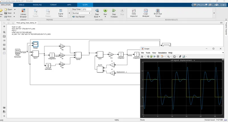
Setting the value of ki between 400-1000.
-Code;
clc
clear all
m=3.6;% mass of system
k=400;% stiffness constant
c=100;% damping constant
A=[0 1;-k/m -c/m]; % matrice A & B from the eqn
B=[0;1/m];
wn=2*pi;% natural frequency
%wn=sqrt(k/m);
%zeta= c/(2*wn*m);
zeta= c /(2*sqrt(k*m))% damping coefficient.
%zeta=1.31;
P1=-zeta*wn + wn*sqrt(zeta^2 -1);% poles of system
P2=-zeta*wn - wn*sqrt(zeta^2 -1);
P=[P1;P2]% matrix form
K=place(A,B,P); % finding value of gains Kp & Kd
Kp=K(1) % allocating values
Kd=K(2)
ans:
zeta =
1.3176
P =
-2.8880
-13.6696
Kp =
-257.8777
Kd =
-40.3925
Conclusion:
-since zeta is > 1 it is an overdamped system
-Poles lies on left half therefore the system is stable
Explation:
-Pulse signal is the reference signal or forcing signal generated
-The error signal is feedback signal generated within the loop to provide proper errors by executing the signal.
-The error signal is subtracted from reference signal which further derivated & inetegrates
-The PID control proportional, integrates & derivates the output from the sum block to obtain desired results.
-The output from the PID is summed further with the function to obtain the results.
-THE Kp & Kd values depends upon the poles of the system .Kp=K(1)& kd=K(2)
-The value of gain block or K(i) can be manually adjusted to find the desired results.