Week 8 - Challenge 6 - Core & Cavity Design
->Class A draft
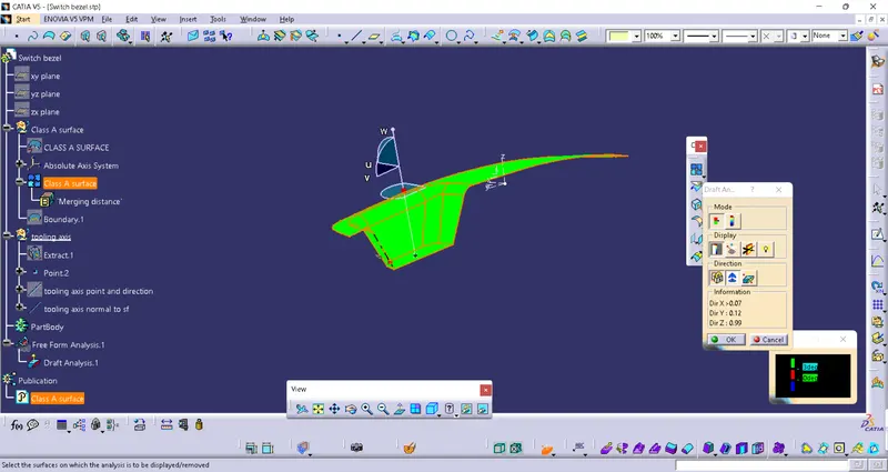
->Final Draft
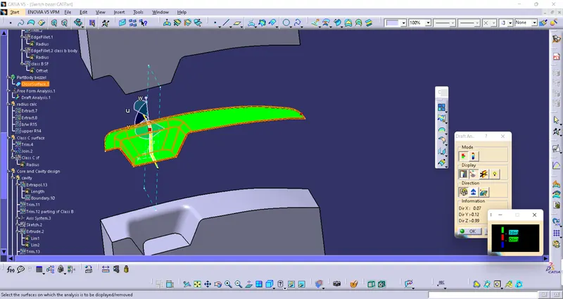
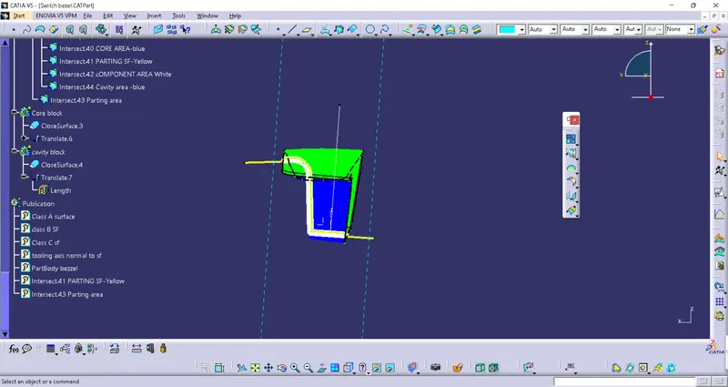
->core cavity block
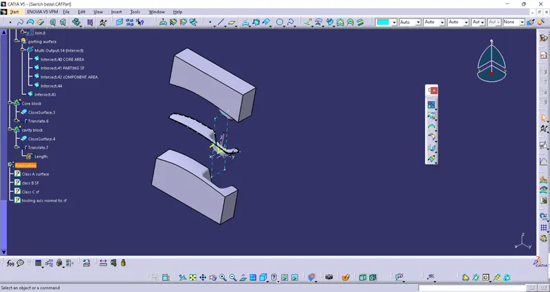
->Intersection
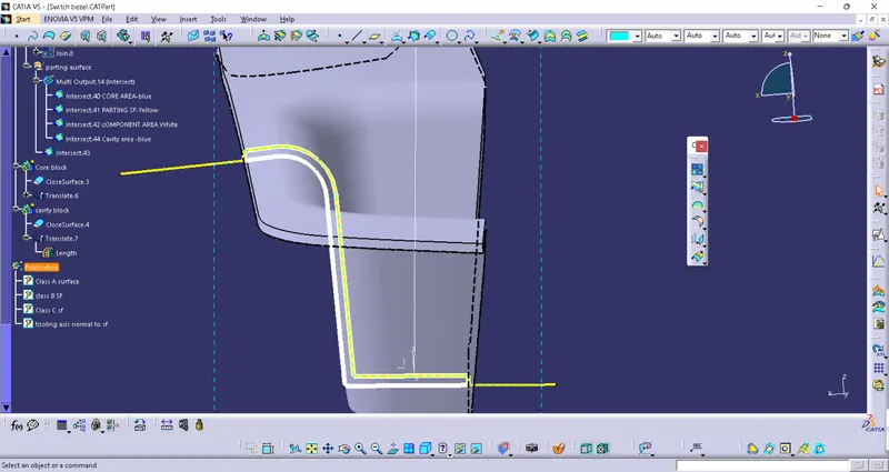
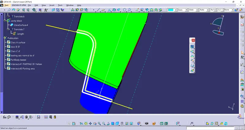
->Creation of tooling axis:
Tooling axis represents the opening and closing of mould or cavity.It indicates how the mould opens or closes. The surface that has projection is called as core while that has depression is called as cavity.In the above example the toooling axis is created using normal to surface methos. Initially the face is extracted ad a point is created on the surface. Followed by normal to surface line command a line is created i.e the tooling axis.
When Complicated parts comes into picture ,tooling axis becomes difficult to create. Therefore for complicated parts we use bisecting method to create tooling axis. In bisecting method 2 opposite surface are intersected using intersect command . The 2 line are drawn inline with the surfaces. Thus an busecting line is drawn using line command by selecting both the line,which creates tooling axis for the surfaces.
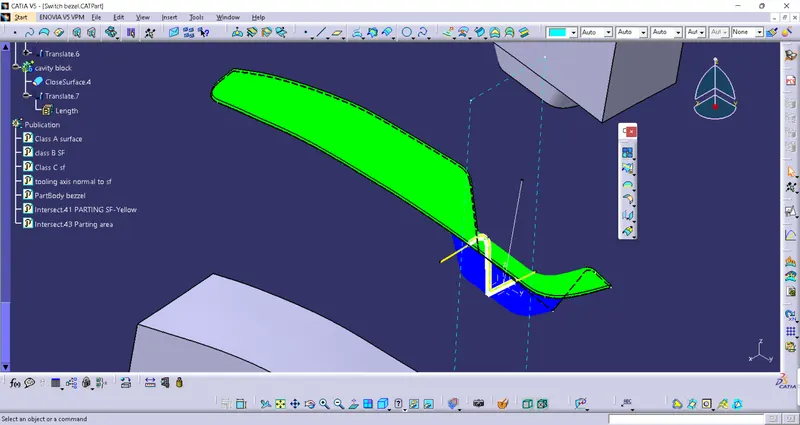
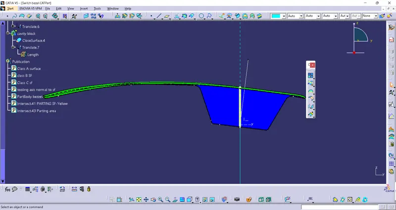
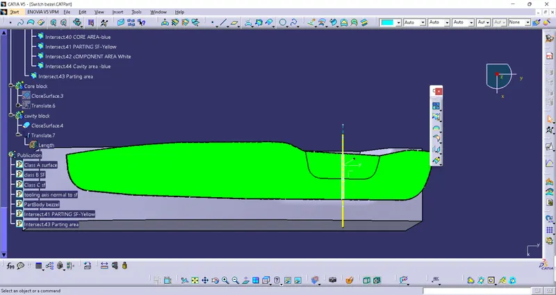
| FV | TV | SV |
 |
 |
 |