Week 8 - Challenge 1 - Base Bracket Design
-> Final Plastic Component
| FV | TV | SV |
 |
 |
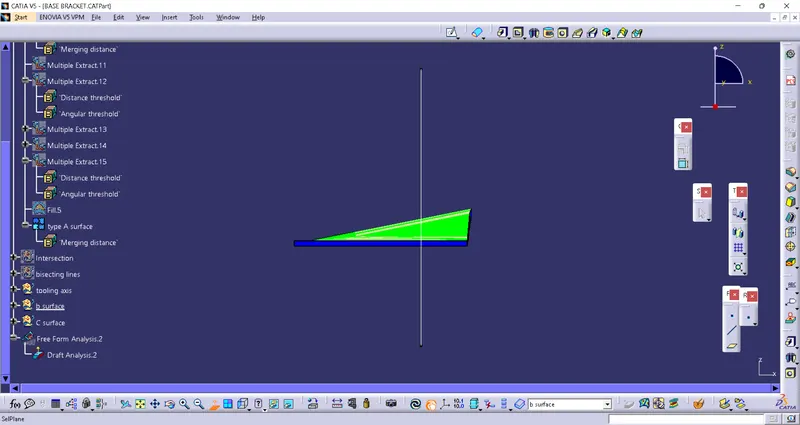 |
-> Class A Surface
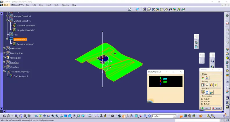
| FV | TV | SV |
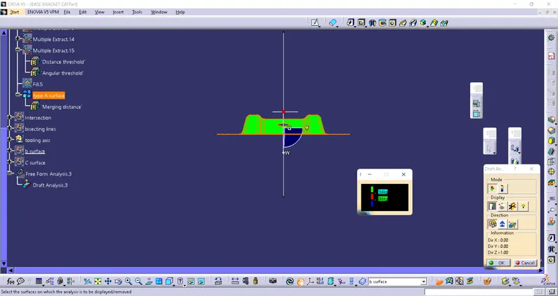 |
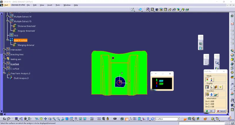 |
 |
-> Creation of tooling axis
- Requirement of tooling axis- Tooling axis is the direction through which mould or cavity opens.
- Tooling axis can either be created by using the dummy point at centre location or by creating th ebisecting lines from curve.
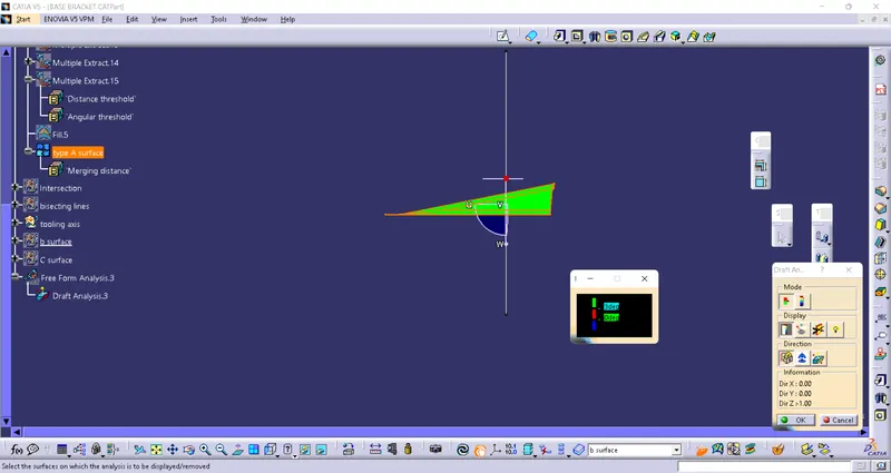
- Considering tooling axis created from curve using bisecting method
Step 1: To verify the continuity of surface.
Checking the continuity of surface , using boundary tool , we neglect the error portion and then create a new surface using extrapollate command followed by fill and join command.
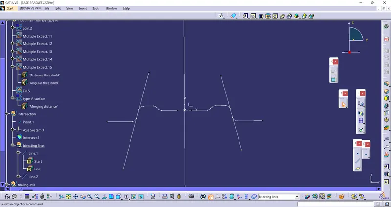
After the correction of surface using and intersection commant an curve is generated.
Taking the best possible centre position the lines are extended through points
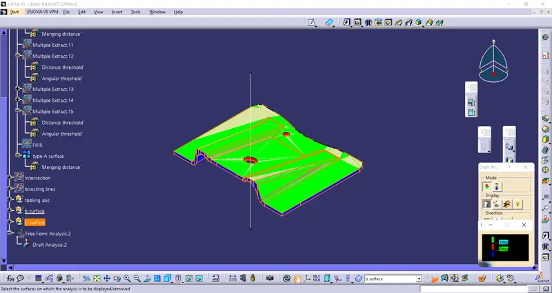
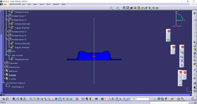
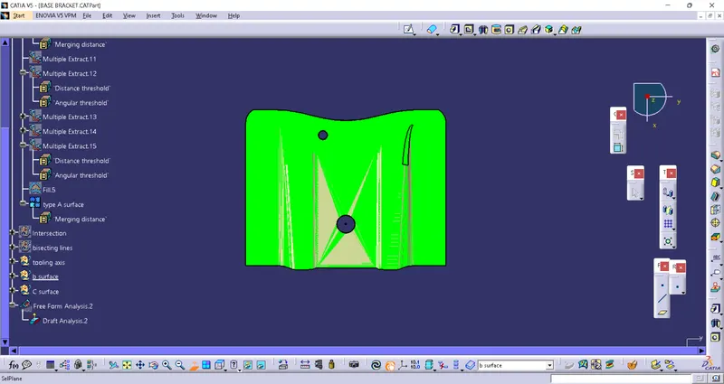
Further by using an bisecting command we get bisecting axis also call as tooling axis.